8.12
Section 8
Disassembly
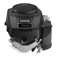
Figure 8-46. Intake Cam Shaft and Oil Pump
Assembly.
6. If necessary, the oil pump can be separated from
the intake side cam sha. Provide appropriate
support for the sha, and drive out the lower
pin. The oil pump assembly can then be removed
from the cam sha. See Figure 8-47.
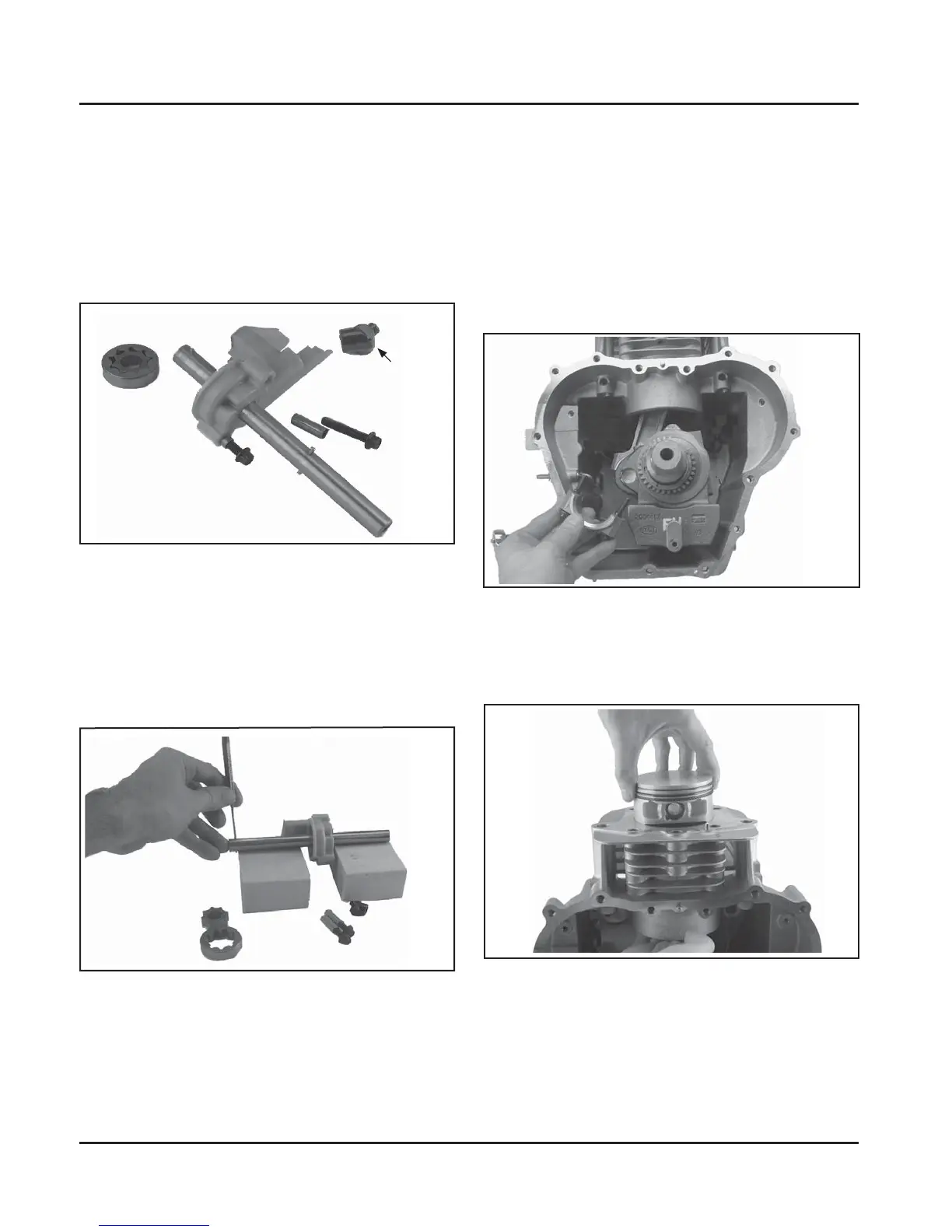
Figure 8-47. Separating Oil Pump Assembly from
Intake Side Cam Shaft.
5. Remove the two screws securing the oil pump
and intake side cam sha to the crankcase. If
a drain back tube is used, it may be unhooked
and removed separately or together with oil
pump. Carefully pull upward on the cam sha to
remove the assembly from the crankcase cavity.
A small rubber oil pump outlet seal on the outlet
of the oil pump may become dislodged during
removal. Do not lose it. See Figures 8-44 and 8-46.
Outlet Seal
(Some Models)
Remove Connecting Rod and Piston
1. Rotate the cranksha so the rod journal is in the
9 o’clock position.
NOTE: If a carbon ridge is present at the top of the
bore, use a ridge reamer to remove it before
aempting to remove the piston.
2. Remove the two hex flange screws and the
connecting rod cap. See Figures 8-48.
Figure 8-48. Removing Connecting Rod Cap.
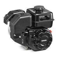
3. Carefully push the connecting rod and the piston
away from the cranksha and out of the cylinder
bore. See Figure 8-49.
Figure 8-49. Removing Piston and Connecting
Rod.