8.14
Section 8
Disassembly
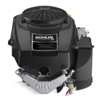
Figure 8-54. Removing Crank Gear Key.
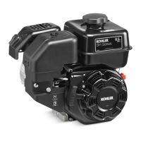
2. Remove the guide shoe from the guide pin on
the flywheel side of the assembly (Before Serial
No. 3618005213). See Figure 8-55. Remove the
link from the guide pin on the PTO side of the
assembly (Aer Serial No. 3618005223). See
Figure 8-56.
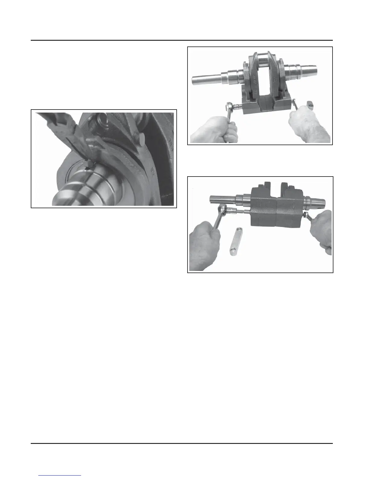
3. Remove the long hex flange screw securing
the two balance weight halves together on the
cranksha. Note the orientation of all parts. The
guide pin is on flywheel side for the balance
weight design with the closure plate side guide
shoe. The guide pin is on PTO side for the
balance weight design with the lower control
link. Hold the guide pin with wrench or torx bit
socket as required. Do not hold or damage the
outside diameter (O.D.) of the guide pin. See
Figure 8-55 or 8-56.
Figure 8-55. Removing Balance Weight Screw
(Guide Shoe Design Before Serial No. 3618005213).
Figure 8-56. Removing Balance Weight Screw and
Guide Pin (Control Link Design After Serial No.
3618005223).
Balance Weight Disassembly
If necessary, the balance weight assembly can be
separated from the cranksha. Disassemble only if
required.
1. Remove the crank gear from the cranksha and
carefully remove the key from the keyway. See
Figure 8-54.