5.10
Section 5
Fuel System and Governor
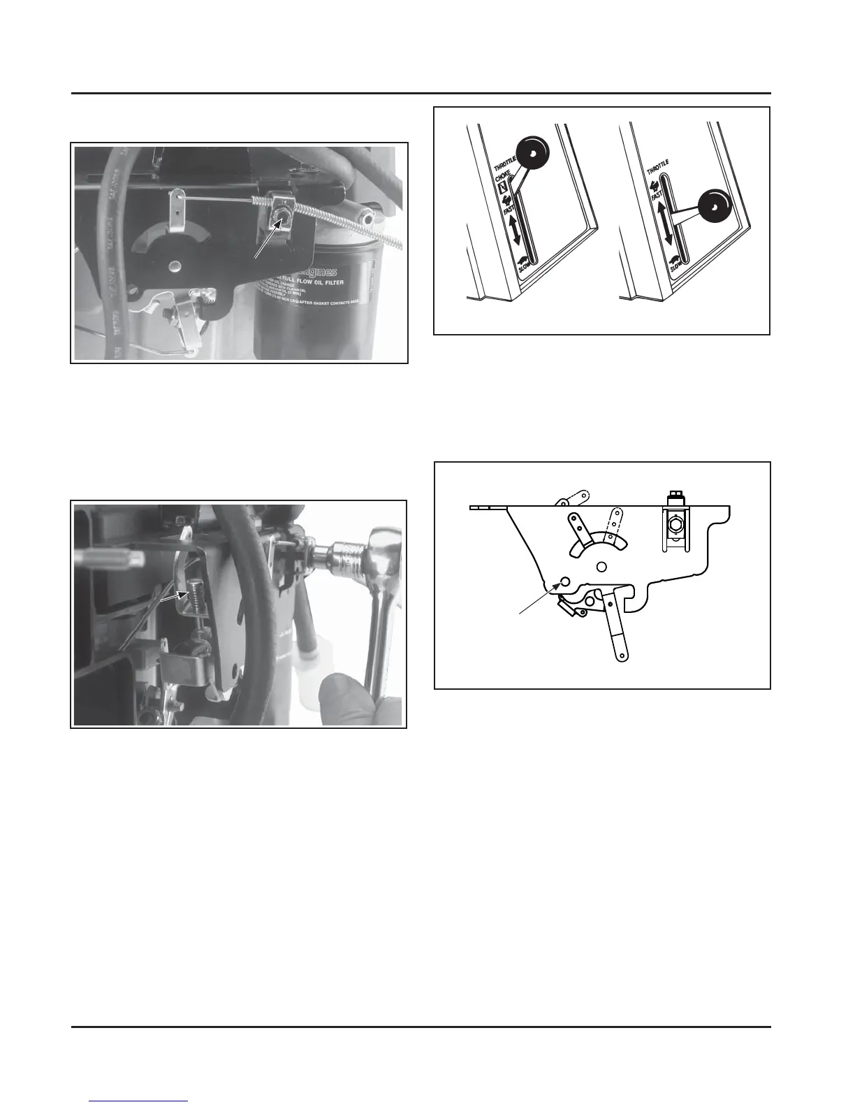
Figure 5-14. Typical Throttle/Choke Controls.
3. Early Models: Early models use a single
alignment hole to set the engine RPM. Align
the hole in the throle lever with the hole in the
speed control bracket by inserting a pencil or 6.35
mm (1/4 in.) drill bit. See Figure 5-15.
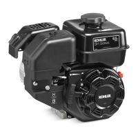
Figure 5-12. Speed Control Bracket with Unitized
Throttle/Choke Control.
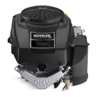
2. Place the throle control lever of the equipment
into the fast or high speed position. The actuating
tab+ of the choke lever should be just below the
end of the choke adjusting screw. See Figure 5-13.
Figure 5-15. Alignment Hole in Speed Control
Bracket and Throttle Lever. (Early Models)
Later Models: Later models use a new control
assembly, identified by two opposing alignment
holes (close to the throle lever pivot), instead of
one. Based upon the intended high-speed (RPM)
seing, throle cable adjustment must be made
by matching the hole in the control lever with the
correct alignment hole. Use the lower (le side)
hole for high-speed seings above 3000 RPM. Use
the upper (right side) hole for high-speed seings
lower than 3000 RPM. Move the throle lever to
align the hole in the lever with the correct hole in
the control bracket. Insert a pencil or a 6.35 mm
(1/4 in.) drill bit to hold in position. See Figure
5-16.
Cold Engine
Warm Engine
Choke
Adjustment
Screw
Alignment Hole
Throttle Cable Adjustment
1. Loosen the control cable clamp. See Figure 5-12.
Cable
Clamp
Figure 5-13Adjusting Unitized Throttle/Choke
Control.
NOTE: The choke is placed on by moving the
throle control slightly past the fast
position. If the throle control does not
have a designated choke on position, be
sure to leave sufficient throle control
travel past the fast position. This will
enable the choke to be placed on. See
Figure 5-14.
 Loading...