5.14
Section 5
Fuel System and Governor
4. To ensure that the RPM has been obtained, move
the throle lever to low idle/slow then back to
full throle/fast position and check the RPM with
a tachometer.
Setting the Low Idle RPM
1. Move the application control to slow position.
2. Using a tachometer, check the RPM. Then, using
a screwdriver, turn the low idle speed screw (see
Figure 5-3) inward (clockwise) to increase the
RPM, and outward (counterclockwise) to lower
the RPM.
Governed Idle Adjustment
A governed idle control system was supplied as
a option on early engines and is standard on later
model engines. The purpose of this system is to
maintain a desired idle speed regardless of ambient
conditions (temperature, parasitic load, etc.) that may
change. The later models can be identified by the two
opposing alignment holes, (adjacent from the throle
lever pivot) rather than one. Based upon the intended
high speed (RPM) seing, cable adjustment must be
made matching the hole in the control lever with the
appropriate alignment hole.
The system requires an additional procedure for
seing the idle speed. If speed adjustments are
required proceed as follows.
1. Make any necessary speed or control adjustments
following the appropriate instructions already
covered in this section.
2. Move the throle control to the idle position.
Hold the governor lever away from the
carburetor, so the throle lever is tight against the
idle speed adjusting screw. Check the speed with
a tachometer and adjust it to 1500-1750 RPM.
3. Release the governor lever and allow the engine
to return to the governed idle speed. Check
it with a tachometer against the equipment
manufacturers recommended idle speed. If
adjustment is necessary, use the governed idle
adjusting screw on the speed control assembly
(see Figure 5-23). Turn the screw clockwise
to increase the governed idle speed and
counterclockwise to decrease it.
Starting an Engine Equipped with Separate
Control Cables
1. Place the throle control midway between the
slow and fast positions. Place the choke control
into the on position.
2. Start the engine.
3. For a Cold Engine – Gradually return the choke
control to the off position aer the engine starts
and warms up.
The engine/equipment may be operated during
the warm up period, but it may be necessary
to leave the choke partially on until the engine
warms up.
4. For a Warm Engine – Return choke to off position
as soon as engine starts.
Changing the High Speed (RPM) on the Engines
with Separate Controls (Increase or Decrease
RPM)
1. Check that the governor spring and installation
matches the intended high speed RPM operating
range. Refer to Figure 5-27 or 5-28.
2. Start the engine, move the application throle
lever to full throle/fast, and loosen the mounting
screws of the main speed control bracket to allow
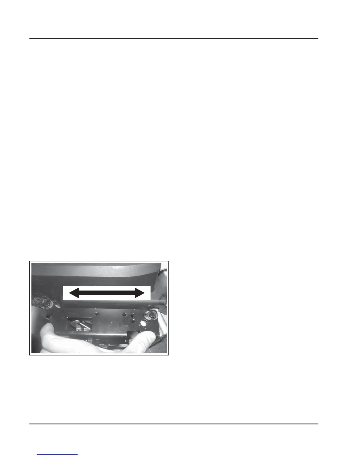
repositioning. See Figure 5-22.
Figure 5-22. Adjusting High Speed (RPM).
3. To increase the RPM: Move the speed control
bracket, towards the carburetor. To decrease the
RPM: Move the speed control bracket, away from
the carburetor. Check the RPM with a tachometer
and tighten screws when correct seing has been
obtained. See Figure 5-19.
 Loading...