7.14
Section 7
Electrical System and Components
Blade Stop Stator Brake Circuit
The blade stop stator brake circuit is provided as a safety feature to ensure the application can meet ANSI
(American National Standards Institute) application blade stop requirements.
The circuit is activated if the operator gets o of the seat of the application while mower blade system is activated
or in certain reverse mow conditions.
The circuit is activated by taking the ignition shutdown (kill) lead to ground. This action turns on the stator-brake
relay which shorts the charging AC stator leads to produce a magnetic eld that will counter or resist the rotation
of the ywheel. This added resistance to rotation decreases the amount of time it takes for the application deck
blades to come to a full stop.
As the Kohler blade stop stator brake circuit oen is operated in conjunction with other application circuits, the
relay in the Kohler circuit is specially congured with a 680 ohm resistor in parallel with the relay coil. This is
done to negate transient voltage signals that would be normally created by interrupting the relay current once
the relay has been activated. Therefore, relay replacement must only be made with the properly identied relay.
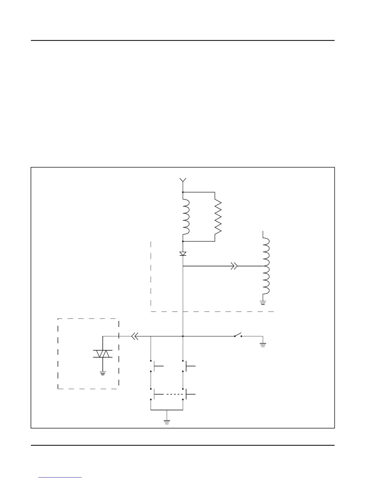
Figure 7-12. Blade Stop Stator Brake Circuit Wiring Diagram.
12V Switched Power
Stator
Brake
Relay
Coil
90 Ω
680 Ω
Engine
Kill
CDI
Ignition
Reverse Mow Module
(OEM Supplied)
TRIAC
NO
PTO
NO
Seat
NC
Brake
NC
Key Switch
 Loading...