TP-6714 4/1040 Section 3 Operation
3.13.1 Fault Reset
To clear a fault or warning condition and reset the
System Alert LED, go to the Main screen and press the
down arrow button to open the Reset screen. See
Figure 3-18 and Figure 3-20. Then press the button
labeled Reset. A fault reset does not change the
controller settings.
See Section 3.14, Accessory Module Faults, for
instructions to correct and reset faults related to the I/O
modules and other accessory modules.
Fault Message
LD Exer ##/## @ ##:##
Norm ###V Emer ###V
B View Set Test
Reset
Fault Description
BYReset Main
When a fault message
is displayed, press the
down arrow
(B) button
on the Main screen to
step to the Reset Fault
screen.
Then press the Reset
button.
Figure 3-20 Fault Reset
3.14 Accessory Module Faults
3.14.1 Module Status Change
Connecting or disconnecting one or more accessory
modules can cause the Module S tatus Change
message to be displayed.
Module Connection (new or reconnected module)
Installing or reconnecting one or more accessory
modules triggers the Module Status Change message.
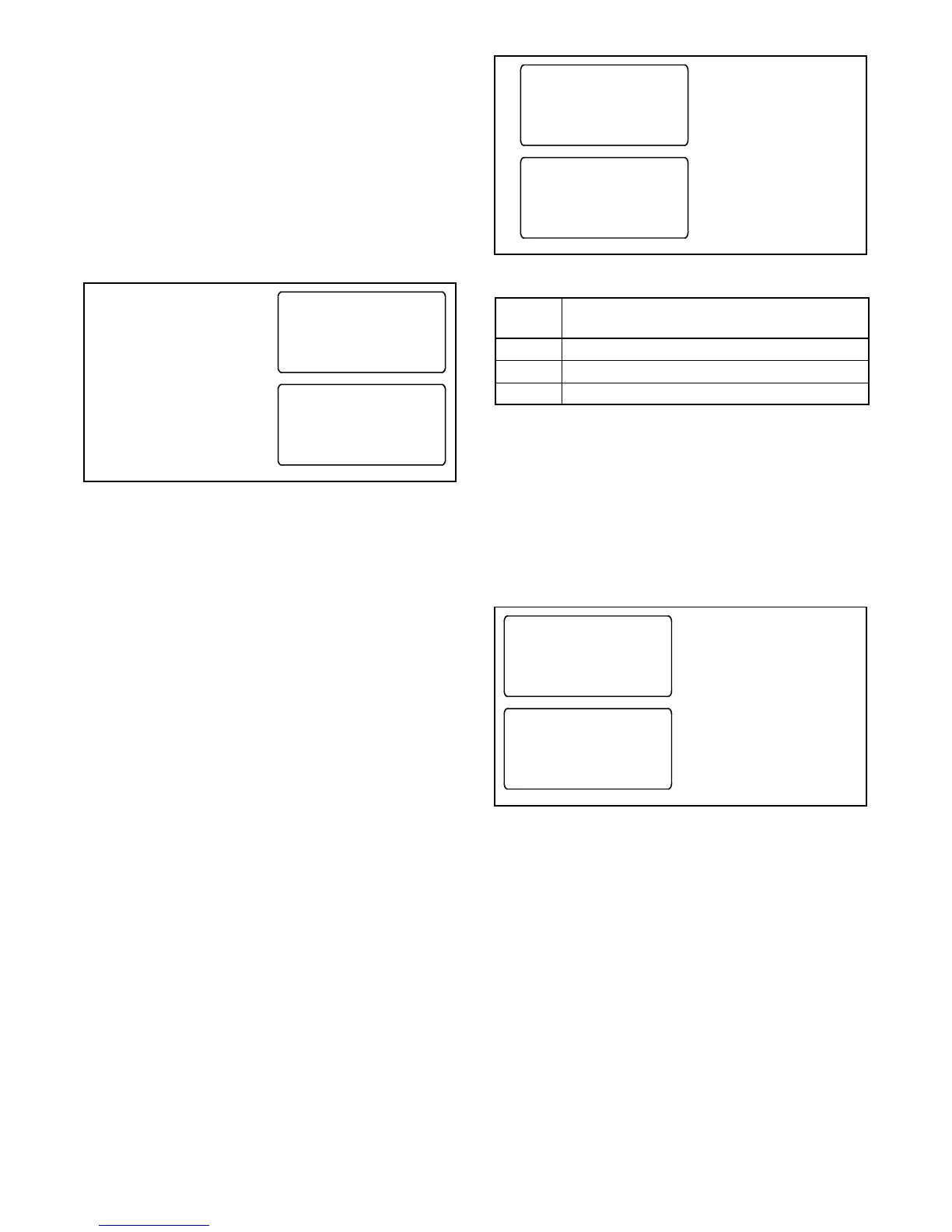
See Figure 3-21. Press the Reset button to display
Reset New Module. Press the Reset button from that
screen. The controller recognizes the module type(s).
See Figure 3-22.
Navigate to the Set Input/Outputs>Set Aux I/O screen to
check that the controller has recognized the connected
modules.
See Section 5.12 for instructions to assign
programmable inputs and outputs to I/O modules. Go to
Section 5.13 for instructions to assign functions to the
audible alarm for an Alarm Module.
Module Status Change
Norm ###V Emer ###V
Reset View Set Test
Reset
New Module
BYReset Main
Press Reset.
Press Reset.
Figure 3-21 Screens after Module Connection
Module
Type
Description
AOB
Switch/Alarm Module (alarm option board)
SOB
Standard I/O Module (standard option board)
POB
High-Power I/O Module (power option board)
Figure 3-22 Module Types
Disconnected Module
If one or more accessory modules are disconnected
from the controller, the message Module Status Change
appears. See Figure 3-23. Pressing the Reset button
displays the message Check Module Setup to Clear
Fault. Use the following Module Uninstall Procedure to
uninstall modules after disconnection.
Module Status Change
Norm ###V Emer ###V
Reset View Set Test
Check Module Setup
to Clear Fault
BYReset Main
Press Reset.
Press Main and follow
Module Uninstall
Procedure.
Figure 3-23 Screens after Module Disconnection

 Loading...


