STEERING AXLE DISASSEMBLY AND ASSEMBLY
40-42 EX20 Series
STEERING AXLE
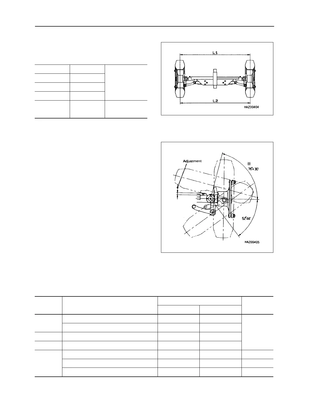
Adjusting alignment
Toe–in L
1
= L
2
Tire turning angle
1. Adjust the left and right stopper bolts so that turning
angle is 76° ± 30'.
2. After adjusting the turning angle, operate the cylinder
in and out and check that there is no scuffing at the
link connection or any other part.
INSPECTION
Toe–in mm
0
Camber deg
Castor deg
King pin angle deg
Tread mm
1,900 (10 t)
1,890 (11.5 t–15 t)
1,870 (16 t)
Symbol Inspection item
Judgement standard
Remedy
Standard size (mm) Repair limit (mm)
A
A1 Outside diameter of center pin 80 79.5
Replace
A2 Inside diameter of center pin bushing 80 80.5
B Outside diameter of king pin 60 59.7
C
Outside diameter of power steering cylinder pin
25 24.7
D
D1 Outside diameter of knuckle mounting pin 30 29.7
D2 Up–down play knuckle 0.1–0.3 0.5 Adjust shim
D3 Inside diameter of mounting pin bushing 30 31.5 Replace
 Loading...