TESTING AND ADJUSTING
EX20 Series 20-7
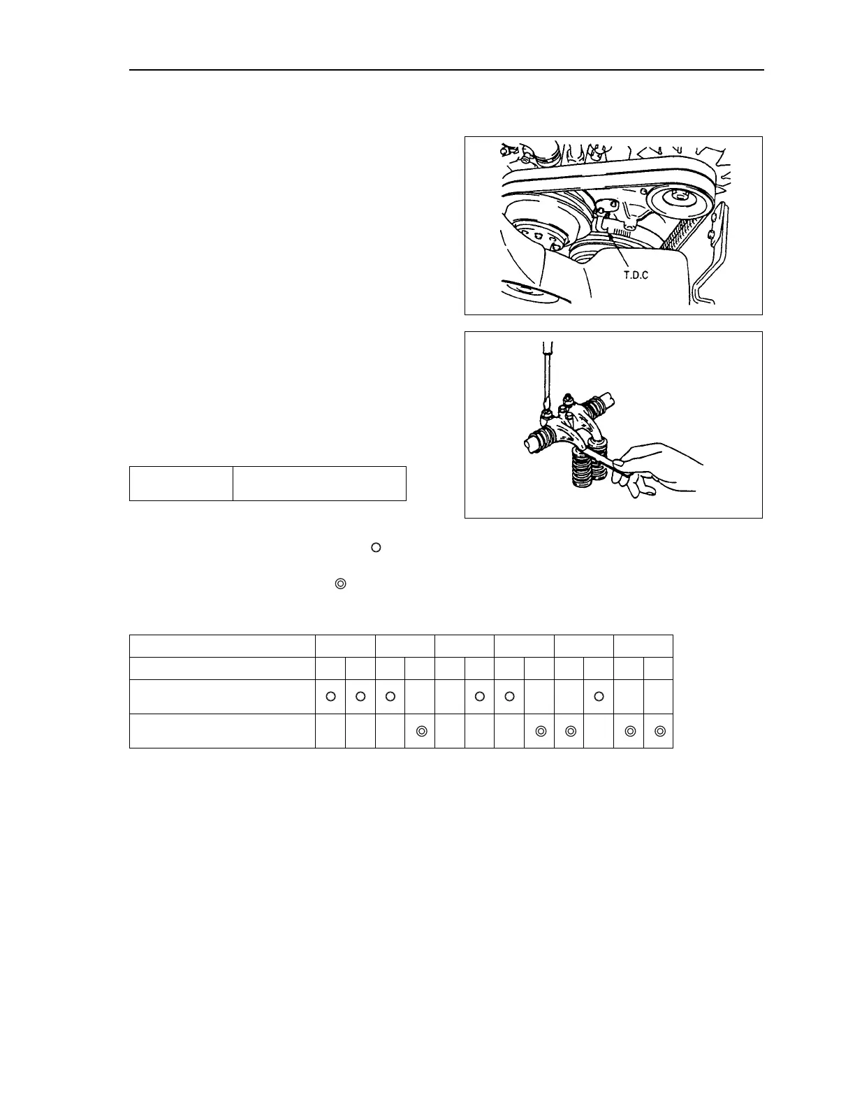
ADJUSTING OF VALVE CREARANCE
Bring the first or sixth piston to the compression top dead
center (T.D.C).
Rotate the crankshaft forward to match the “T.D.C. line” of
the pulley damper to the “pointer”.
At this time, check that there is “clearance” between the
respective rocker arms and intake and exhaust valves of
the first or sixth cylinder. (The cylinder having “clearance”
between the respective rocker arms and intake and
exhaust valves is at the compression top dead center.)
Adjusting of valve clearance
Adjust the valve clearance of the cylinder at the compres-
sion top dead center, then adjust the valve clearance of
the other cylinders in order. Insert a thickness gauge in
the clearance between the inlet and exhaust valve stems
and their respective rocker arms, and adjust the clear-
ance with their respective adjustment screws.
When starting adjusting with the first cylinder, adjust the
valve clearance of the valves indicated with " ". When
starting adjusting with the sixth cylinder, adjust the valve
clearance of the valves indicated with " ".
Valve clearance
Both intake and exhaust
valves: 0.4 mm (in cold state)
Cylinder No. 123456
Valves arrangement IEIEIEIEIEIE
When No. 1 cylinder is at
compression top dead center
When No. 6 cylinder is at
compression top dead center
ADJUSTING OF VALVE CREARANCE
 Loading...