Commissioning
24
Pos: 17.10 /Übersc hriften/Überschrif ten 2/A-E/ AAnbau an den Traktor @ 0\ mod_1199717 845194_78.docx @ 34039 @ 2 @ 1
5.3 Mounting onto the Tractor
Pos: 17.11 /Übersc hriften/Überschrif ten 3/K-O/ KKuppelpun kte @ 9\mod_12 20531326398 _78.docx @ 1266 08 @ 3 @ 1
5.3.1 Clutching points
Pos: 17.12 /BA/Ers tinbetriebna hme/Mähwerke AM Baureihe/Es g ibt 3 Anbau möglichkeiten @ 72\mod_1 30745462148 2_78.docx @ 6510 58 @ @ 1
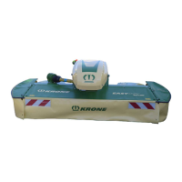
There are 3 ways to attach the mowing unit:
Pos: 17.13 /BA/Ers tinbetriebna hme/Mähwerke AM Baureihe/Ku ppelpun kte Bild AM-S Kat. II @ 69\mod_1 30503690747 7_78.docx @ 6326 16 @ @ 1
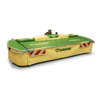
Fig.
Pos: 17.14 /BA/Ers tinbetriebna hme/Mähwerke AM Baureihe/a) Kat. II Kupp elpunkte Te xt AM S und AM C V Baureihe @ 6 9\mod_13050 36909040_78.d ocx @ 632644 @ @ 1
a) Cat. II
The standard setting of the steerable pinions is for Cat. II.
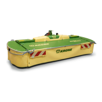
Pos: 17.15 /BA/Ers tinbetriebna hme/Mähwerke AM Baureihe/Ku ppelpunkte Bild AM-S K at.I @ 73\mod _13081441455 46_78.docx @ 655231 @ @ 1
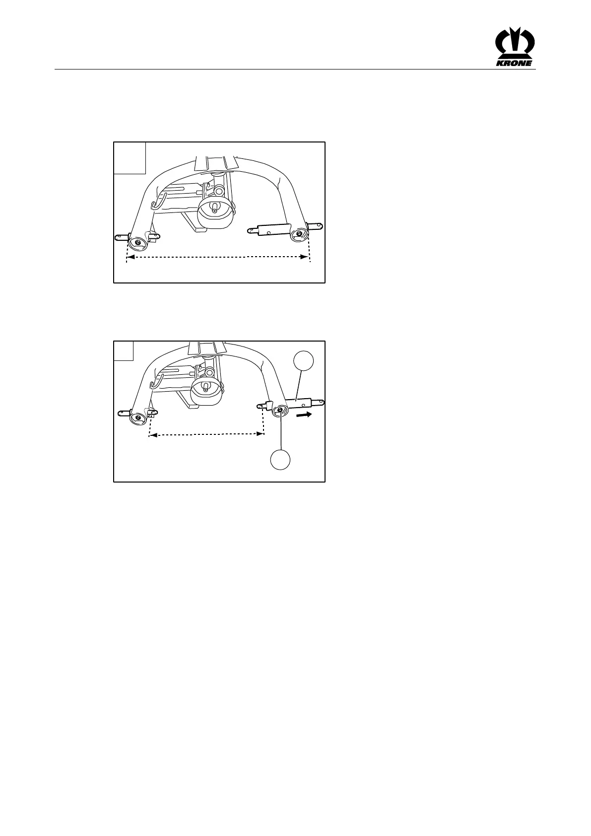
Fig.
Pos: 17.16 /BA/Ers tinbetriebna hme/Mähwerke AM Baureihe/b) Kat. I Kuppel punkte Text AM 203S/243S/2 83S/323S @ 69\ mod_130503 7666765_78.doc x @ 632720 @ @ 1
b) Cat. I
For Cat. I the steerable pinion (1) must be offset to the outside.
To do this:
• Remove the screw (2)
• Offset the steerable pinion (1) outwards
• Tighten the screw (2) again
Pos: 17.17 /La yout Module /---------------Seitenumbruch---------------- @ 0\mod_11961 75311226_0.doc x @ 4165 @ @ 1
 Loading...