2-S7
F2880, F3680, RCK72-F36, RCK72R-F36, RCK60-F36, RCK60R-F36, WSM
TRANSMISSION
4. CHECKING, DISASSEMBLING AND SERVICING
[1] CHECKING AND ADJUSTING
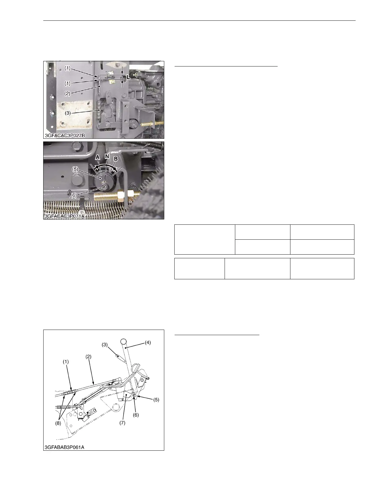
Adjustment of HST Neutral Position
1. Check the adjusting screw length (L). If measurement is not
within the factory specifications, adjust the adjusting screw (2).
2. Lift the front and rear of machine so that the front and rear wheels
are off the ground.
3. Remove the right front wheel.
4. Run the engine at low idle speed.
5. Loosen the holder shaft mounting screw (6).
6. Rotate the holder shaft (5) counterclockwise so that the front axle
shafts turn forward.
7. Then rotate it clockwise until the front axles stop completely.
8. Put a mark on the side frame (Position A).
9. Rotate the holder shaft (5) clockwise so that the front axle shafts
turn reverse.
10.Then rotate it counterclockwise until the front axles stop
completely.
11.Put a mark on the side frame (Position B).
12.Set the holder shaft (1) where it is right in the center between
position A and B, and tighten the holder shaft mounting screw (6)
firmly.
This means the hydrostatic transmission is fully in neutral.
(Position N)
W1011821
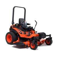
Adjusting Speed Control Rod
■
• Before adjusting the neutral of HST, adjust the brake
system.
1. After adjusting the neutral of HST, pull the parking lock lever (3).
2. Check that the groove of brake lock (5) engages with the pin of
speed control bracket (6) smoothly.
3. If not, adjust the length of speed control rod (2) with the
turnbuckle (1).
■
• After adjustment, secure the turnbuckle (1) with the lock
nuts (8).
W1021165
Adjusting screw length
“L”
Factory spec.
15.0 mm
0.59 in.
Allowable limit
15 to 20 mm
0.59 to 0.79 in.
Tightening torque
Holder shaft mounting
screw
23.5 to 27.4 N·m
2.40 to 2.79 kgf·m
17.4 to 20.2 ft-lbs
(1) Adjusting Lock Nut
(2) Adjusting Screw
(3) Neutral Spring
(4) Plate
(5) Holder Shaft
(6) Holder Shaft Mounting Screw
L : Adjusting Screw Length
A : Position A
B : position B
N : Position N
(1) Turnbuckle
(2) Speed Control Rod
(3) Parking Lock Lever
(4) Main Brake Pedal
(5) Groove of Brake Lock
(6) Pin of Speed Control Bracket
(7) Speed Control Bracket
(8) Lock Nut