7-M6
F2880, F3680, RCK72-F36, RCK72R-F36, RCK60-F36, RCK60R-F36, WSM
HYDRAULIC SYSTEM
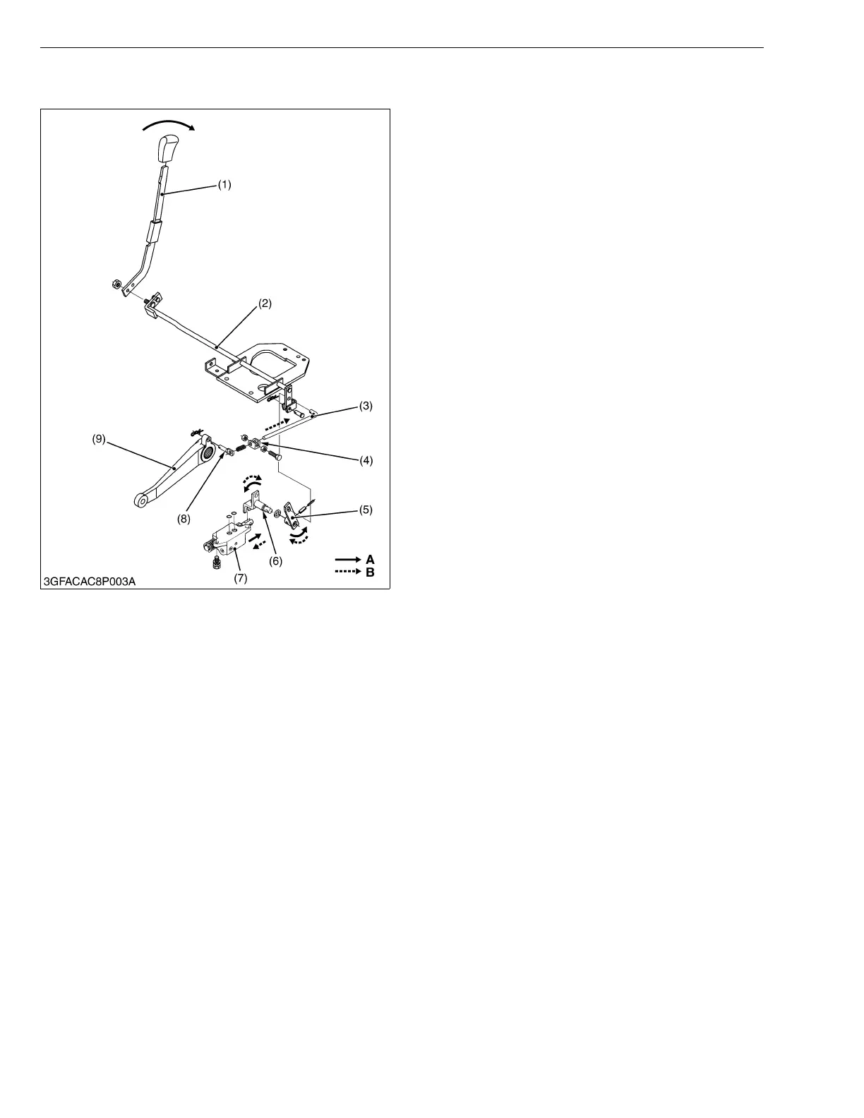
6. FEEDBACK LINKAGE
When the hydraulic control lever 1 (1) is moved to
rearward to lift the implement, the spool of the implement
control valve (7) is pulled out to form a raising circuit.
Then the lift arm (9) begins to rise.
After the lift arm (9) gets to the uppermost position,
the spool is pushed in and returned to form a neutral
circuit by the motions of the feedback pin (8), feedback
rod (3), hydraulic control lever 2 (2), control lever arm (5)
and control lever shaft (6).
W1014224
(1) Hydraulic Control Lever 1
(2) Hydraulic Control Lever 2
(3) Feedback Rod
(4) Interlocker
(5) Control Lever Arm
(6) Control Lever Shaft
(7) Implement Control Valve
(8) Feedback Pin
(9) Lift Arm
A : When the hydraulic control
lever is moved to rearward
B : When the lift arm gets to the
uppermost position
 Loading...