8-S11
F2880, F3680, RCK72-F36, RCK72R-F36, RCK60-F36, RCK60R-F36, WSM
ELECTRICAL SYSTEM
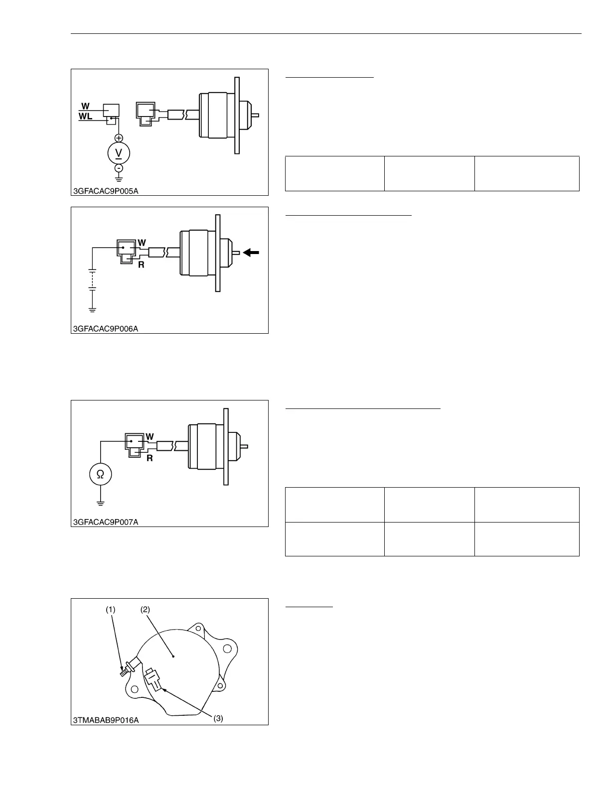
(7) Engine Stop Solenoid
Connector Voltage
1. Disconnect the 2P connector from the engine stop solenoid.
2. Turn the main switch key to the “ON” position, and measure the
voltage with a voltmeter between the connector terminal (White/
Blue) and the chassis.
3. If the voltage differs from the battery voltage, the wiring harness
or main switch is faulty.
W1020004
Engine Stop Solenoid Test
1. Disconnect the 2P connector from the engine stop solenoid.
2. Remove the engine stop solenoid from the engine.
3. Connect the jumper leads from the battery positive terminal to the
connector terminal (White), and from the battery negative
terminal to the chassis.
4. If the solenoid plunger is not retracted, the engine stop solenoid
is faulty.
5. Connect the jumper leads from the battery positive terminal to the
connector terminal (Red), and from the battery negative terminal
to the chassis.
Push the solenoid plunger in by your finger, and then release it.
6. If the solenoid plunger is not held, the engine stop solenoid is
faulty.
7. If the engine stop solenoid is faulty, replace it.
W1020102
Engine Stop Solenoid Continuity
1. Disconnect the 2P connector from the engine stop solenoid.
2. Measure the resistance with an ohmmeter between the
connector terminal and the chassis.
3. If the factory specifications are not indicated, the engine stop
solenoid is faulty.
4. If the engine stop solenoid is faulty, replace it.
W1020224
(8) Charging System
Alternator
1. Disconnect the 2P connector (3) from alternator after turning the
main switch OFF.
2. Perform the following checkings.
W1016691
Voltage
(Connector terminal -
Chassis)
Factory spec. Approx. battery voltage
Resistance
[Connector terminal
(White) - Chassis]
Factory spec. Approx. 0.4 ohms
Resistance
[Connector terminal
(Red) - Chassis]
Factory spec. Approx. 1.5 ohms
(1) B Terminal
(2) Alternator
(3) 2P Connector

 Loading...