HYDRAULIC SYSTEM
L3560, L4060, L4760, L5060, L5460, L6060, WSM
8-S20
[3] POSITION CONTROL VALVE
(1) Separating Control Valve
Separating Hydraulic Block Assembly
• See page 8-S19.
9Y1210824HYS0024US0
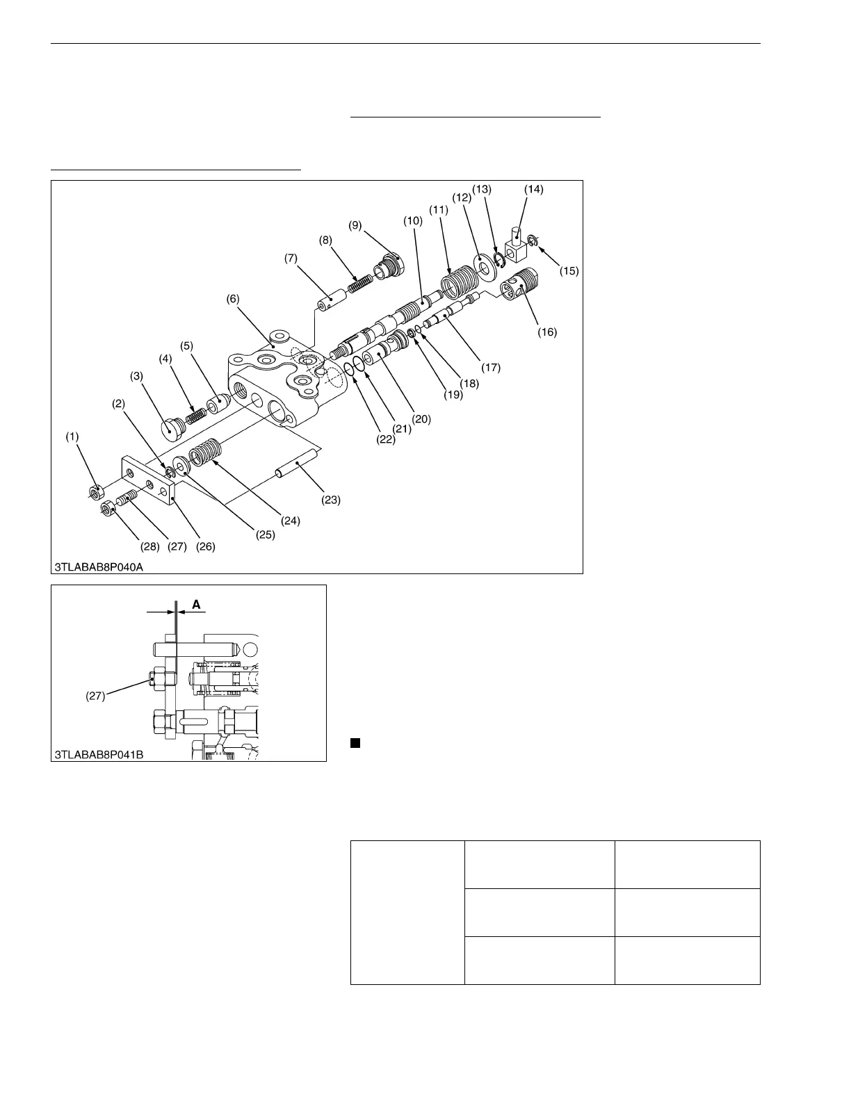
Disassembling Position Control Valve
1. Remove the nut (1), and draw out the spool (10).
2. Remove the unload plug (3), and draw out the spring (4), unload
poppet (5).
3. Remove the plug 2 (9), and draw out the spring (8), unload
poppet 2 (7).
4. Remove the external snap ring (2), spring seat (25) and spring
(24).
5. Remove the plug 1 (16), and draw out the poppet 2 (17), sleeve
(20).
• Do not loosen the adjusting screw (27) unless necessary.
If disassembled due to unavoidable reasons, be sure to set
the dimension "A" to 0.2 mm (0.008 in.).
(When reassembling)
• Be careful not to damage the backup ring and O-rings.
9Y1210824HYS0025US0
(1) Nut
(2) External Snap Ring
(3) Unload Plug
(4) Spring
(5) Unload Poppet
(6) Valve Body
(7) Unload Poppet 2
(8) Spring
(9) Plug 2
(10) Spool
(11) Spring
(12) Plain Washer
(13) External Snap Ring
(14) Spool Joint
(15) External Snap Ring
(16) Plug 1
(17) Poppet 2
(18) O-ring
(19) Backup Ring
(20) Sleeve
(21) O-ring
(22) O-ring
(23) Dowel Pin
(24) Spring
(25) Spring Seat
(26) Connecting Plate
(27) Adjusting Screw
(28) Nut
Tightening torque
Unload plug
40 to 58 N·m
4.0 to 6.0 kgf·m
29 to 43 lbf·ft
Plug 2
40 to 58 N·m
4.0 to 6.0 kgf·m
29 to 43 lbf·ft
Plug 1
40 to 58 N·m
4.0 to 6.0 kgf·m
29 to 43 lbf·ft
 Loading...


