ELECTRICAL SYSTEM
L3560, L4060, L4760, L5060, L5460, L6060, WSM
9-S60
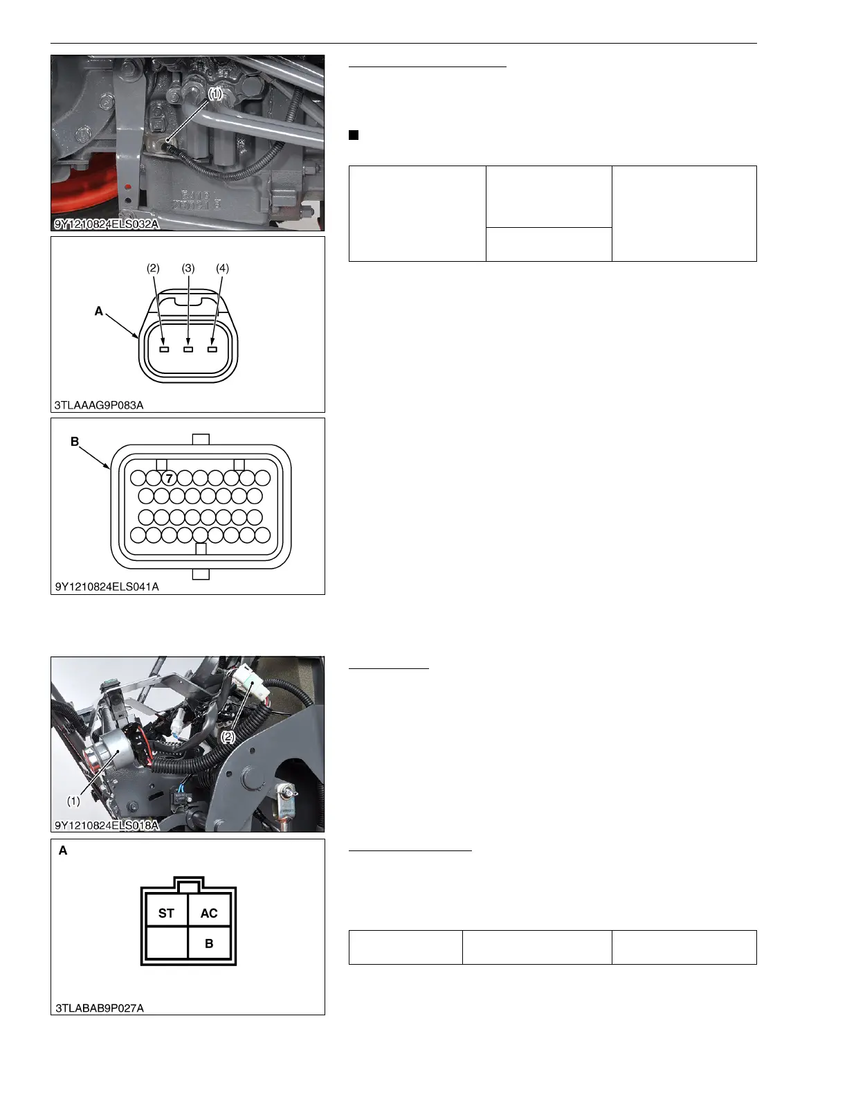
Traveling Speed Sensor
1. Measure the resistance between terminal 7 of main ECU
connector B and terminal 2 of sensor connector.
2. If 0 ohm is not indicated, the wiring harness is faulty.
• It is not necessary to adjust any kind of mode.
9Y1210824ELS0058US0
[6] STARTING SYSTEM
(1) Main Switch (ROPS Type)
Main Switch
1. Remove the panel cover.
2. Disconnect the main switch connector (2).
3. Perform the following checking.
9Y1210824ELS0059US0
Connector Voltage
1. Measure the voltage across the connector B terminal and
chassis.
2. If the voltage differs from the battery voltage (11 to 14 V), the
wiring harness is faulty.
9Y1210824ELS0060US0
Resistance
Ter mi na l 2 of sensor
connector – Terminal 7
of main ECU
connector B
0 Ω
Ter mi na l 3 of sensor
connector – Chassis
(1) Traveling Speed Sensor
(2) Terminal 1
(3) Terminal 2
(4) Terminal 3
A : Connector of Wire Harness Side
B : Main ECU Connector B (34P) of
Wire Harness Side
(1) Main Switch (2) Main Switch Connector
Voltage
Connector B terminal –
Chassis
Approx. battery voltage
A: Wire Harness Side Connector 4C
 Loading...


