Do you have a question about the LTH Electronics MXD75 and is the answer not in the manual?
| Screen Size | 75 inches |
|---|---|
| Resolution | 3840 x 2160 (4K UHD) |
| Aspect Ratio | 16:9 |
| Input Voltage | 100-240 VAC, 50/60 Hz |
| Operating Temperature | 0°C to 40°C |
| Storage Temperature | -20°C to 60°C |
| Brightness | 400 cd/m² |
| Viewing Angle | 178° (H) / 178° (V) |
| Weight | 35 kg |
Details on connecting power supply and standard outputs to the instrument.
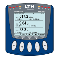
Overview of the instrument's user interface, including display, buttons, and status indicators.
Explains the security access pop-up for protecting instrument setup.
Details compliance with European EMC Directive 2014/30/EU using BS EN 61326-1: 2013.
Outlines safety compliance with the European Low Voltage Directive 2014/35/EU using BS EN 61010-1: 2010.
Illustrates the termination points on the rear of the MXD73 instrument, showing connector layouts.
Lists the available options for current outputs, expandable up to 4 or 6.
Provides specifications for selectable 0-20mA or 4-20mA outputs, isolated to 2kV.
Details options for setpoints and control relays, expandable up to 4 or 6 relays.
Covers safety and electromagnetic compatibility aspects of instrument installation.
Guides the selection and mounting of conductivity sensors for optimal performance and representative samples.
Provides instructions and cautions for wiring the instrument, emphasizing power isolation and earth connection.
Details the care and maintenance procedures for conductivity sensors, including cleaning and checks.
Explains how to connect AC or DC supply voltage to the unit, including daisy-chaining.
Explains how to connect current outputs (A to F) with details for different expansion cards.
Details how to connect relays (1-6) which are electrically isolated from the instrument.
Information on connecting the Modbus RS485 interface, referring to the accompanying handbook.
Information on connecting various compatible sensors to the unit.
Allows users to select their own access code or disable the security system by setting it to 0000.
Customizes the information displayed on the front screen, including channel display and labels.
Initiates the software update process if required files are present on the SD card.
Details how to unlock optional software functions using an 8-digit unlock code.
Guides users through setting up live trend screens, including number of traces and range.
Enables logging of instrument status to an SD card, with configurable channels and logging interval.
Allows users to view logged data from the SD card by selecting time and date.
Displays the SD card data logging graph, allowing scrolling through logged data by time.
Instructions on how to view SD card data logs on a PC using file explorer and Microsoft Excel.
Provides detailed descriptions of errors and suggested solutions for possible causes.
Configures basic parameters for the conductivity sensor input, including Mode, Units, and Range.
Enables temperature compensation by setting the mode to 'In'.
Details calibration using standard solutions under strictly controlled conditions.
Adjusts the sensor reading to match a known input.
Describes USP operation for conductivity measurements according to FDA requirements.
Sets the 'Channel' and 'Trigger' for USP operation.
Guides through channel calibration setup, including mode, units, and manual inputs.
Configures setpoints, including input source, trigger, high/low values, mode, and delay.
Configures current outputs, including input source, range, zero, and span.
Lists errors related to digital input configurations.
Sets up service reminders, intervals, and alarm dates for instrument maintenance.
Lists errors related to communication failures between cards and the unit.
Lists errors related to calculation configurations.
Lists errors related to Modbus communication setup and data storage.
Lists internal error messages with probable causes and solutions.
Lists errors related to input cards, setup checksums, and sensor calibration.
Continues listing input channel errors, including signal issues and sensor calibration deviations.
Notifies when the planned service interval has expired.
Lists various errors related to setpoint configurations.
Lists errors related to current output circuits and parameters.
Lists errors related to digital input configurations.
Troubleshooting steps for sensor readings that are consistently over or under the expected range.
Checks for open/short circuits, cable damage, and secure connections when display reads zero.
Steps to troubleshoot instrument display malfunctions, including power cycling.
Details the warranty terms for the MXD70 Series against defects in materials and workmanship.
Outlines the limitations and exclusions of the product warranty.
Details the specifications for the Dissolved Oxygen Input Card, including measurement types and ranges.
Guides the selection and mounting of Dissolved Oxygen sensors for optimal performance.
Details connections for 2, 3, and 4 wire RTD temperature sensors.
Configures basic parameters for the Dissolved Oxygen sensor input, including mode and units.
Outlines normal good practices for calibrating DO systems.
Starts the dissolved oxygen sensor's zero calibration process.
Starts the dissolved oxygen sensor's span calibration.
Details specifications for the Suspended Solids Input Card, including supported sensor types and linearization.
Details specifications for the Turbidity Input Card, including supported sensor types and linearization.
Guides the selection and mounting of suspended solids/turbidity sensors.
Configures basic parameters for the suspended solids/turbidity sensor input.
Details calibration procedures for suspended solids/turbidity sensors.
Enables direct entry to calibration menu from front screen.
Configures a calibration interval that triggers an alarm upon expiry.
Resets user calibrations to their default states for the selected channel.
Provides guidance for diagnosing and correcting faults that may occur during normal operation.
Troubleshooting steps for an instrument that appears dead, checking power and connections.
Addresses issues with incorrect or forgotten access codes.
Troubleshooting steps for sensor readings that are consistently over or under the expected range.
Troubleshooting steps for incorrect sensor readings, including immersion and probe condition.
Troubleshooting for incorrect or noisy current output issues, checking load and wiring.
Checks relay status, setpoint configuration, hysteresis, connections, and noise interference.
Explains how to configure setpoints, including input source, trigger, high/low values, and modes.
Details the configuration of current outputs (A-F), including assignment to sensor input channels.
Describes the setup functions for eight digital inputs, including assignment to channels and functions.
Guides through setting up the Modbus communication mode, slave address, and baud rate.
Provides a comprehensive list of Modbus registers for instrument configuration and sensor readings.