14 ENGLISH
NOTE:Dependingontheconditionsofuseandthe
ambienttemperature,theindicationmaydifferslightly
fromtheactualcapacity.
Automatic speed change function
NOTE:Automaticspeedchangefunctionisonly
availablewhenthespeedadjustingdialisin5.
Thistoolhas"highspeedmode"and"hightorque
mode".
Thetoolautomaticallychangestheoperationmode
depending on the work load. When the work load is low,
thetoolwillruninthe"highspeedmode"forquicker
cutting operation. When the work load is high, the tool
willruninthe"hightorquemode"forpowerfulcutting
operation.
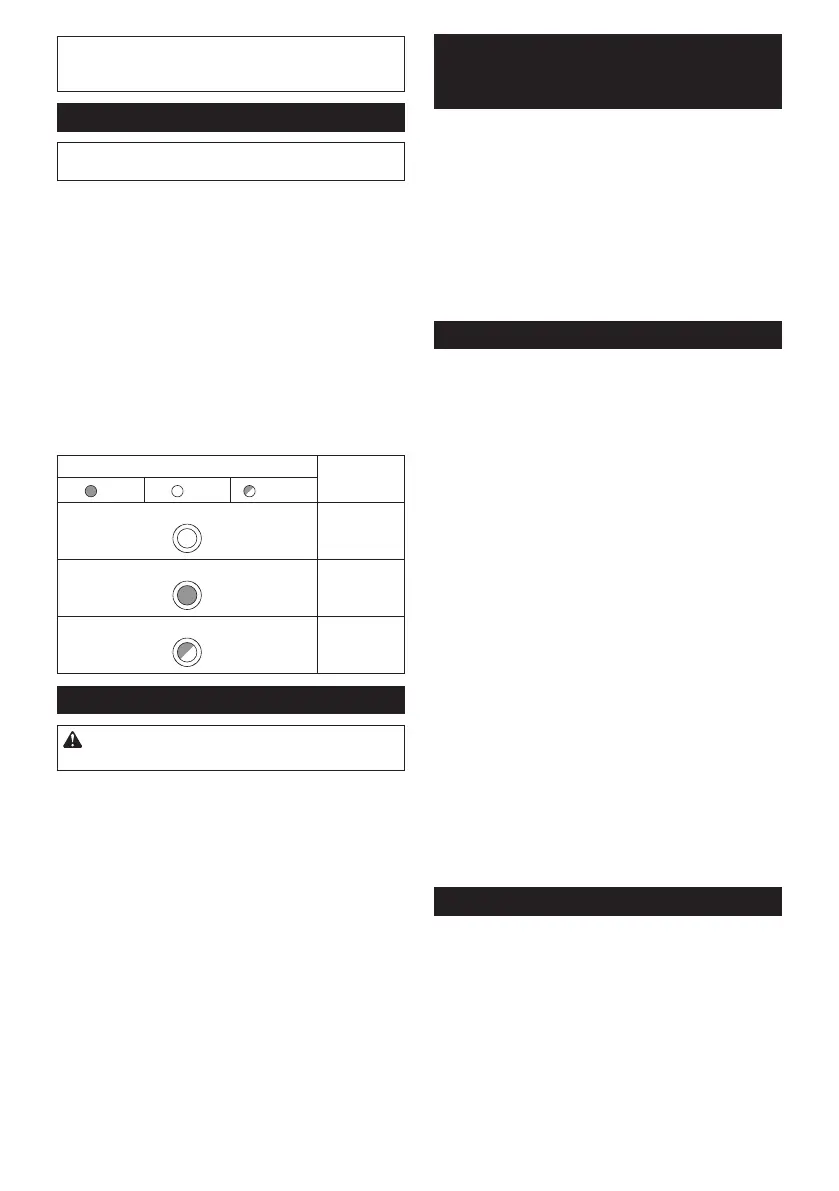
►Fig.10: 1. Mode indicator
Themodeindicatorlightsupingreenwhenthetoolis
runningin"hightorquemode".
Ifthetoolisoperatedwithexcessiveload,themode
indicatorwillblinkingreen.Themodeindicatorstops
blinkingandthenlightsuporturnsoffifyoureducethe
load on the tool.
Mode indicator status Operation
mode
On Off Blinking
High speed
mode
Hightorque
mode
Overload
alert
Adjusting depth of cut
CAUTION: After adjusting the depth of cut,
always tighten the clamping screw securely.
Loosen the clamping screw on the depth guide and
move the blade lower limit stopper to the desired depth
onthescaleplate.Atthedesireddepthofcut,tighten
theclampingscrewrmly.
Forcleaner,safercuts,setcutdepthsothatnomore
thanonebladetoothprojectsbelowworkpiece.Using
propercutdepthhelpstoreducepotentialfordanger-
ousKICKBACKSwhichcancausepersonalinjury.
►Fig.11: 1. Blade lower limit stopper 2. Clamping
screw
Quick stop button for 2 to 3 mm
depth of cut when using guide rail
(optional accessory)
Thistoolhasthequickstopbuttonfor2to3mmdepth
ofcutonthegearhousingasidetherearhandlewhen
usingguiderail.Thisisusedwhenavoidingsplinteron
theworkpieceinthecut.Makeapassofthe2to3mm
rstcutandthenmakeanotherpassofusualcut.
►Fig.12: 1. Quick stop button
Toobtainthe2to3mmdepthofcut,pushinthequick
stopbuttontowardthesawblade.Thisisconvenientfor
avoiding splinter on the workpiece.
Toreleasethedepthofcutfromthispositionforfree
depthofcut,justpullthebuttonback.
Bevel cutting
Loosentheclampingscrews.Setforthedesiredangle
by tilting accordingly, then tighten the clamping screws
securely.
►Fig.13: 1. Clamping screw 2. Bevel scale plate
►Fig.14: 1.Subbase(Optionalaccessory)
2. Clamping screw
Positive stopper
Thepositivestopperisusefulforsettingthedesignated
anglequickly.Turnthepositivestoppersothatthe
arrow on it points 22.5°. Loosen the clamping screws
infrontandback.Thentiltthebladeuntilitstopsand
secure the base with the clamping screws.
►Fig.15: 1. Positive stopper 2. Clamping screw
48°-bevel cutting
Toperform48°-bevelcutting,loosentheclamping
screwsandfullytiltthelevertowardthedirectionofthe
arrowinthegure.Thensetthebevelangleto48°and
tighten the clamping screws.
►Fig.16: 1. Lever
-1°-bevel cutting
Toperform-1°-bevelcutting,loosentheclamping
screwsandpresstheleverstowardthedirectionofthe
arrowinthegure.Thensetthebevelangleto-1°and
tighten the clamping screws.
►Fig.17: 1. Lever
Sighting
►Fig.18: 1. Base
Thecuttinglinevariesdependingonthecuttingangle
andwhetheryouusetheguiderail(optionalaccessory).
When using the tool without guide rail
Forstraightcuts,aligntheApositiononthefrontofthe
base with your cutting line. For 45° bevel cuts, align the
B position with it.
When using the tool with guide rail
For both straight cuts and 45° bevel cuts, always align
theApositiononthefrontofthebasewithyourcutting
line.
 Loading...