Manitowoc Published 05-16-17, Control # 233-03 2-27
999 SERVICE/MAINTENANCE MANUAL HYDRAULIC SYSTEM
counterweight pins, swing lock, swing brake, travel brakes,
and travel 2-speed. Reconnect all electrical connections
(DIN plugs) that were disconnected for hydraulic system
checks.
1. Drum pawls:
a. Place each drum park switch in on – park and off –
park positions.
b. Observe that each drum pawl engages and
disengages correctly.
2. Counterweight pins:
a. Access setup remote control in left side enclosure.
b. Use counterweight pins switch on remote control to
engage and disengage cylinders several times to
remove air from system.
3. Swing brake and swing lock:
a. Scroll to swing diagnostic screen.
b. With swing park brake and swing lock off, attempt to
swing the crane by moving control handle in both
directions.
c. Crane must respond and indicate on swing screen
that swing park brake and swing lock are released.
4. Travel brakes:
a. Scroll to travel diagnostic screen.
b. With travel park brake off, attempt to travel the
crane by moving control handles in both directions.
c. Crane must respond and indicate on travel screen
that travel park brake is released.
d. Travel 2-speed is checked in test area when travel
speed is checked.
Travel Handle and Speed Check
Verify that travel movement responds correctly to handle
commands. You must count number of revolutions crawler
rotates in one minute to determine travel speed.
NOTE: Final evaluation of travel system is completed in
test area.
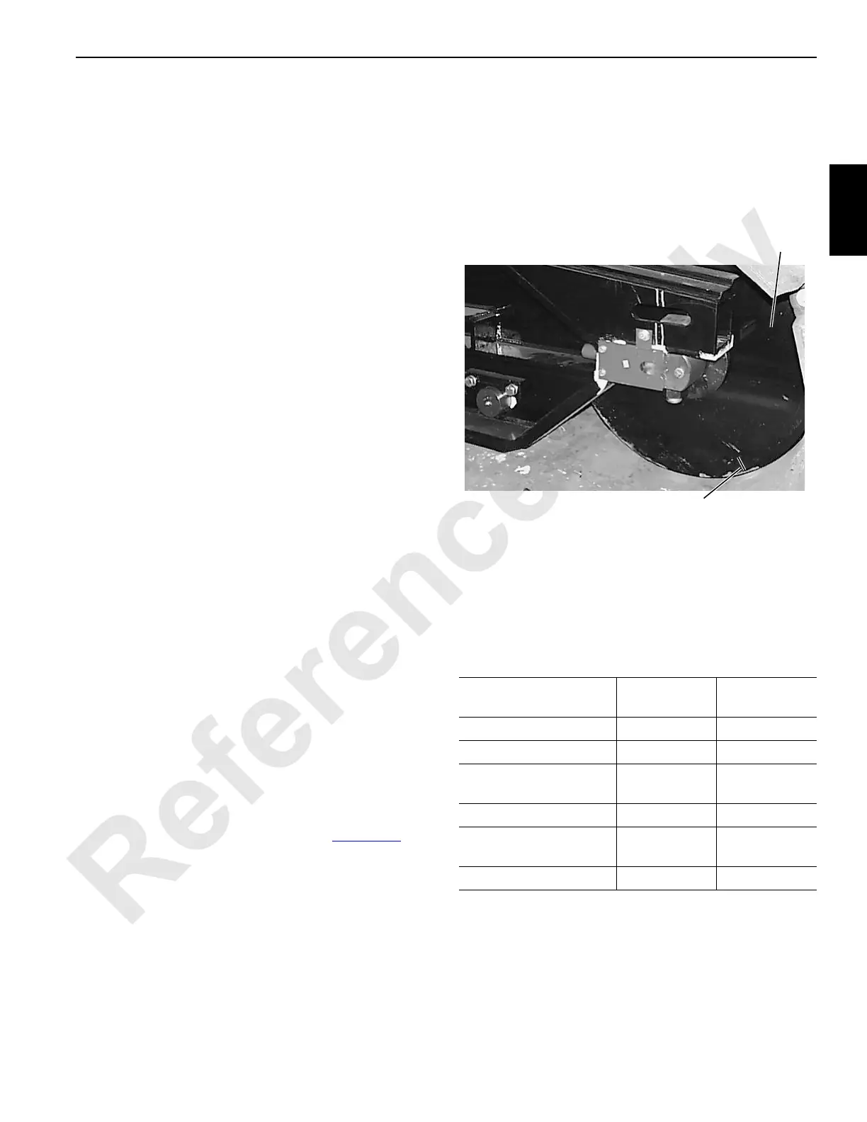
1. Put a timing mark on either front roller (Figure 2-24
).
2. Start engine and set speed at high idle.
3. Push both crawler control handles fully forward to travel
crane forward at full speed.
4. Have an assistant count number of revolutions timing
mark makes.
5. Number should be 8-1/2 – 9 revolutions in one minute
(tumbler or idler) or as indicated on Final Checkout/
Assembly and Test form.
6. If count does not fall within this range, determine cause
of problem and take corrective action.
Operating Drum Speed Checks
Check operating speeds for functions listed below with
engine running at high idle and control handles moved fully
forward and back. Read speeds on digital display screen.
If proper speeds are not indicated, determine cause of
problem and take corrective action.
Item
Speed Up
(rpm)
Speed Down
(rpm)
Boom Hoist 39 – 43 34 – 41
Front Drum 43 – 48 38 – 46
Front Drum
(high line speed)
68 – 75 60 – 71
Rear Drum 43 – 48 38 – 46
Rear Drum
(high line speed)
68 – 75 60 – 71
Auxiliary Drum 64 – 71 57 – 67
FIGURE 2-24
Front Roller
P1426
Timing Mark

 Loading...


