ELECTRIC SYSTEM 999 SERVICE/MAINTENANCE MANUAL
3-8
Published 05-16-17, Control # 233-03
TEST VOLTAGES
This section contains test voltages sorted into four
categories:
Pin Identification. . . . . . . . . . . . . . . . . . . . . . . . . .
page 3-9
Wire Identification . . . . . . . . . . . . . . . . . . . . . . . page 3-13
Description Identification . . . . . . . . . . . . . . . . . . page 3-17
Controller Board Identification . . . . . . . . . . . . . . page 3-21
NOTE: Unused pin connections are not shown.
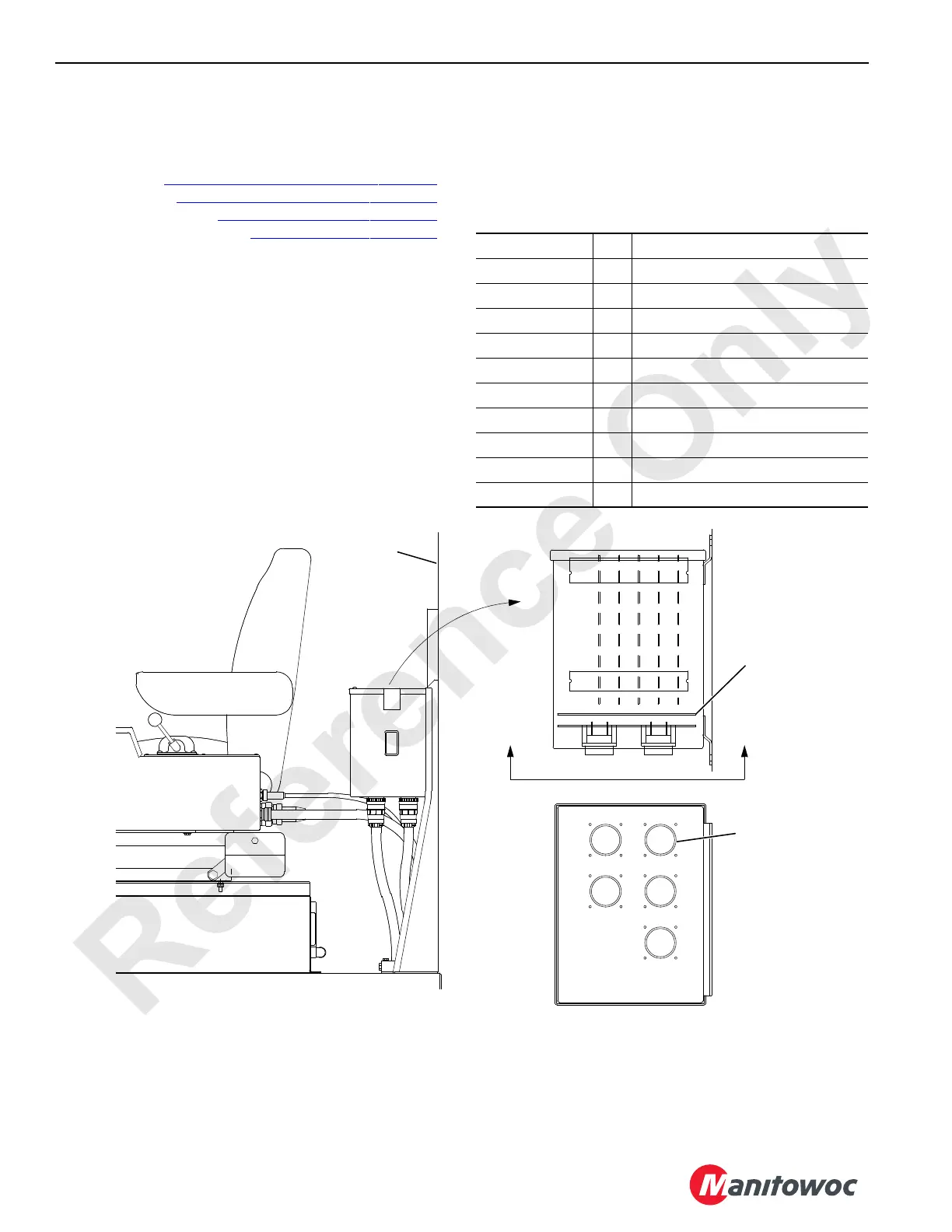
Controller Board Layout
The board locations in the programmable controller are
shown below.
Test Voltage Abbreviations
The following abbreviations are used in this section:
I/O = Input/Output
AI = Analog Input
AO = Analog Output
Press. = Pressure
psi = Pounds per Square Inch
DI = Digital Input
DO = Digital Output
NC = No Connection
CHA or CHB = Channel A or B
COMM = Communication
CPU = Central Processing Unit
E
D
B
C
A
CPU BOARD
I/O BOARD 1
I/O BOARD 2
I/O BOARD 3
I/O BOARD 4
Rear Cab
Wall
Mother
Board
Cable
Connector
A1105
FIGURE 3-8

 Loading...


