Manitowoc Published 05-16-17, Control # 233-03 5-1
999 SERVICE/MAINTENANCE MANUAL HOISTS
SECTION 5
HOISTS
HOIST DRAWINGS
Applicable hoist and load block drawings are attached at the
end of this Section.
WIRE ROPE REMOVAL
To remove wire rope from any load drum, activate limit
bypass switch on front console in cab. This action allows the
drum to be operated in the lower direction when the
minimum bail limit is contacted.
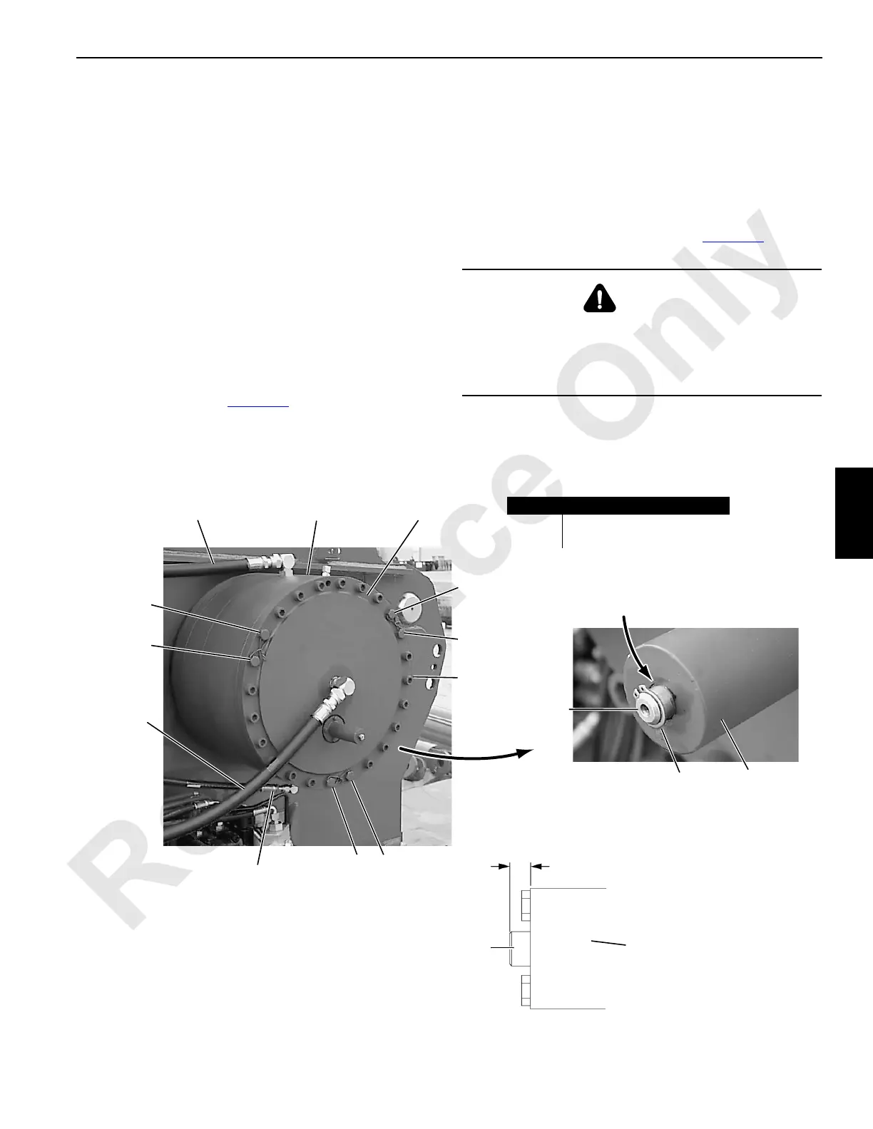
FREE FALL CLUTCH/BRAKE
Either or both load drums can be equipped with a free fall
clutch/brake as shown in Figure 5-1
.
Inspection
Inspect wear indicator with brake applied. Note that wear
indicator moves in as brake discs wear.
Replace brake discs when indicated in Figure 5-1
.
DANGER
Falling Load Hazard!
Free fall clutch/brake will not hold load if brake discs are
worn. To prevent load from falling, inspect each wear
indicator weekly and replace discs when indicated.
P1579
FIGURE 5-1
Brake
Release
Hose
P1578
Clutch/Brake
Assembly
Cover
Coolant
Return
Hose
Coolant
Supply
Hose
4
3
1
5
6
2
7
Ring Indicator
Housing
Wear Indicator
Moves In as
Brake Discs Wear
Item Identification
1- 6 Hex Head Capscrews
7 Socket Head Capscrews
• 7.7 mm (0.30 in) – Brake Discs OKAY
• 1.5 mm (0.06 in) – REPLACE Brake Discs
Wear Indicator
Moves In as
Brake Discs Wear
Indicator
Housing

 Loading...


