INTRODUCTION 999 SERVICE/MAINTENANCE MANUAL
1-38
Published 05-16-17, Control # 233-03
Auxiliary Drum Brake and Pawl Switch
When auxiliary drum brake switch (14) is in on - park position
auxiliary drum pawl in solenoid HS-27 is enabled and pawl
(11) is engaged. Auxiliary drum brake release solenoid HS-
26 is spring-applied to auxiliary drum.
When auxiliary drum brake switch is placed in off - park
position, auxiliary drum pawl out solenoid HS-28 is enabled
and pawl is disengaged from drum. Auxiliary drum brake
remains spring-applied to auxiliary drum and is controlled
automatically by the PC with movement of auxiliary drum
handle.
Release of auxiliary drum brake is from 350 psi (25 bar)
charge pressure supplied from auxiliary charge pump. If
charge pressure drops below 200 psi (14 bar), brakes spring-
apply.
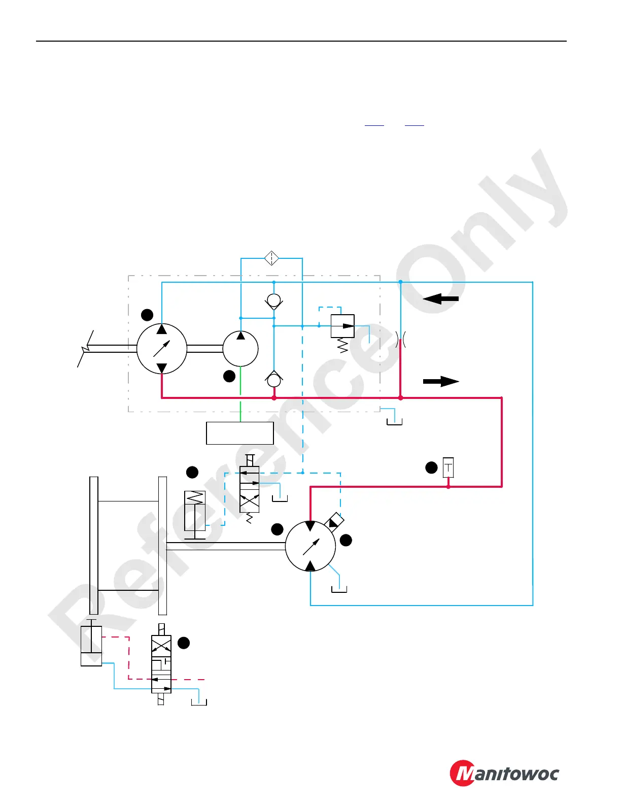
Auxiliary Drum Raise
See Figures 1-26 and 1-27
When auxiliary drum handle (1) is moved back for drum
hoist, handle neutral switch closes, sending an input voltage
of 5 volts or more to PC. The PC sends a positive output
voltage to auxiliary load drum pump EDC (2) and to motor
PCP (6). The PC checks that drum block-up limit switches
(12) are closed with no hydraulic system faults present.
FIGURE 1-27
HS-28
B
A
A
B
LOW PRESSURE SIDE
HIGH PRESSURE SIDE
350 PSI
(24 BAR
)
AUXILIARY
DRUM
LOW PRESSURE
HS-27
BRAKE
PAWL
SUPERCHARGE
MANIFOLD
CHARGE
PUMP
PILOT
AUXILIARY DRUM PUMP
999CSM1-127
3
4
3
10
3
7
3
3
3
13
3
5
.06
HS-26
3
11

 Loading...


