TROUBLESHOOTING 999 SERVICE/MAINTENANCE MANUAL
10-54
Published 05-16-17, Control # 233-03
Test 22 – Checking Hydraulic Brake Pressure
The swing brake, swing lock and travel brakes operate off
rear drum low-pressure charge pump pressure. The front
drum brake, rear drum brake, and boom hoist brake operate
off low-pressure side of each closed-loop system. The
auxiliary drum brake operates off auxiliary low-pressure
charge pump pressure.
To check hydraulic brake pressures for swing and travel
systems:
• Engine must be off and power off, with all brakes and
locks engaged.
• Disconnect a rear drum charge pressure line.
• Connect a 0 – 1,000 psi (69 bar) gauge with tee fitting in
charge pressure line.
• Start engine and set throttle at high idle.
• Enable test system brake and check that brake pressure
is 325 – 375 psi (22 – 26 bar). Charge pressure can also
be checked at system diagnostic screen.
• If pressure is not within range, adjust rear drum charge
pressure (see Test 18).
• Remove pressure gauge and replace the charge
pressure line.
To check hydraulic brake pressure for front drum, rear drum,
or boom hoist system:
• Engine must be off and power off, with all brakes
engaged.
• Connect a 0 – 1,000 psi (69 bar) gauge at diagnostic
gauge coupler on loop flushing valve.
• Start engine and set throttle at high idle (2,000 rpm).
• Enable test system brake and check that brake pressure
is 325 – 375 psi (22 – 26 bar). Charge pressure can also
be checked at system diagnostic screen.
• If pressure is not within range, check system charge
pressure (see Test 18).
• Remove pressure gauge from diagnostic gauge coupler.
To check hydraulic brake pressure for auxiliary drum system:
• Engine must be off and power off, with all brakes
engaged.
• Connect a 0 – 1,000 psi (69 bar) gauge at test port on
auxiliary filter manifold.
• Start engine and set throttle at high idle (2,000 rpm).
• Enable auxiliary drum brake and check that brake
pressure is 325 – 375 psi (22 – 26 bar). Charge pressure
can also be checked at system diagnostic screen.
• If pressure is not within range, check system charge
pressure (see Test 18).
• Remove pressure gauge from test port on auxiliary filter
manifold.
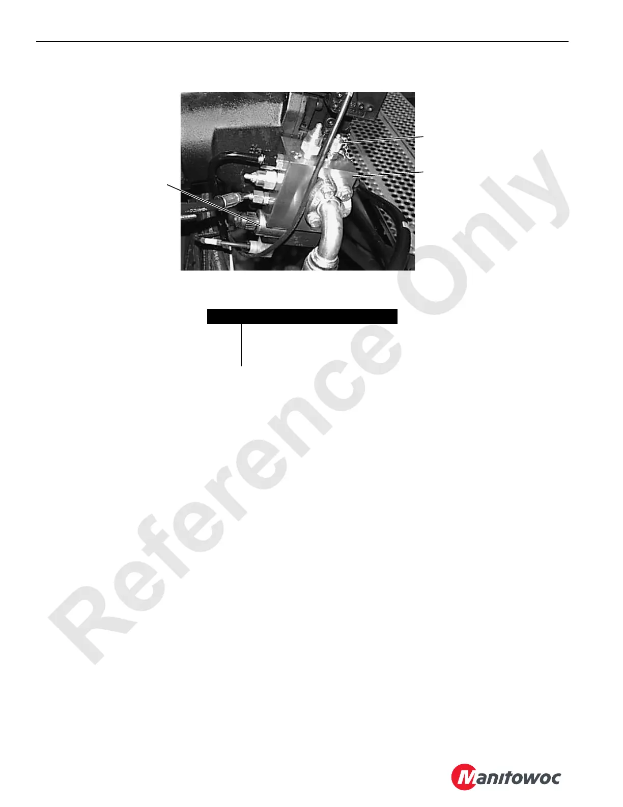
Item Description
1 Diagnostic Gauge Coupler
2 Loop Flushing (purge) Valve
3 Brake Solenoid Valve

 Loading...


