HYDRAULIC SYSTEM 999 SERVICE/MAINTENANCE MANUAL
2-10
Published 05-16-17, Control # 233-03
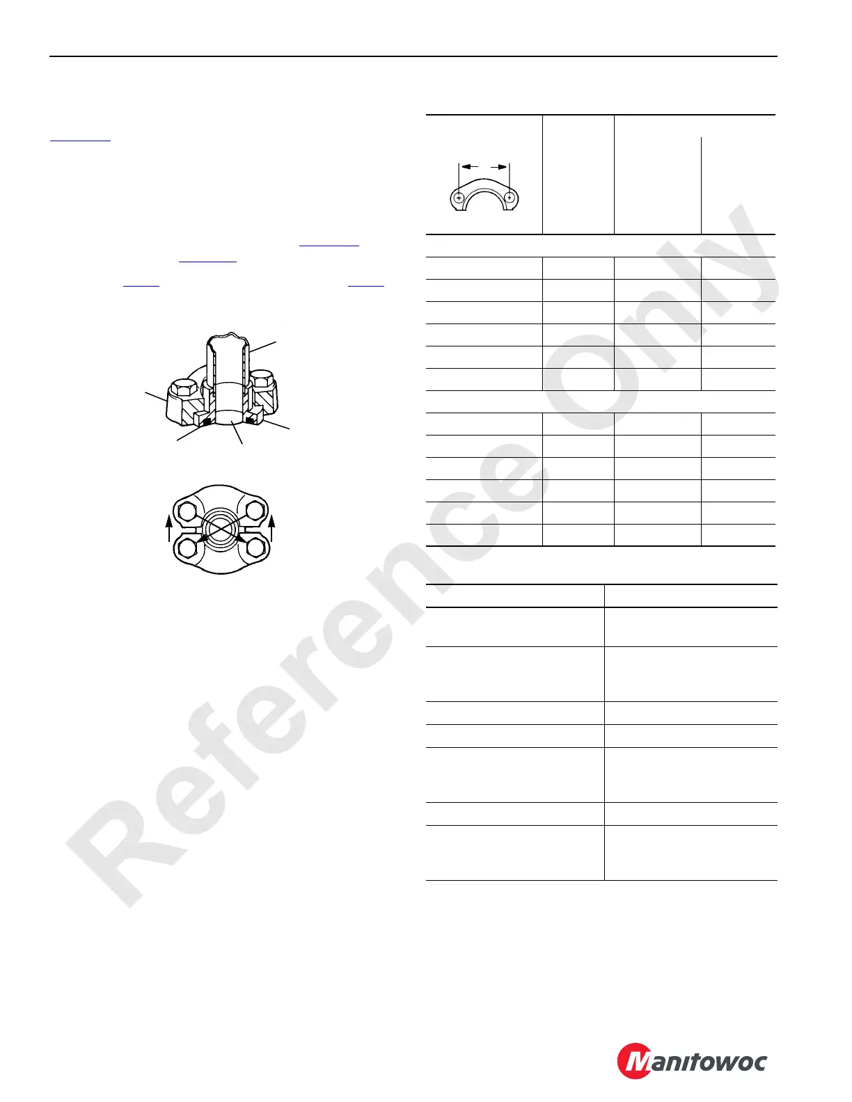
Split Flange Connection
Lubricate and install O-ring in shoulder groove (see
Figure 2-6
).
1. Align shoulder with port and assemble flanges over
shoulder.
2. Bolts used must be grade-5 or better. Grade-5 bolt has
three dashes in head.
3. Snug bolts in a diagonal manner (see Figure 2-6
) to 1/3
of torque given in Table 2-6.
.
4. Repeat step 3
to 2/3 of final torque. Repeat step 3 to
final torque.
Table 2-6. Split Flange Assembly Torque
Table 2-7. Split Flange Leakage
Port
Shoulder
Flange
O-Ring
FIGURE 2-6
S104
1
2
3
4
S101
Tube
"A" Dimension
(inch)
Flange
Size
Torque
in-lb N•m
Standard Pressure Series
1-1/2 -08 175 – 225 20 – 25
1-7/8 -12 225 – 350 25 – 40
2-1/16 -16 325 – 425 37 – 48
2-5/16 -20 425 – 550 48 – 62
2-3/4 -24 550 – 700 62 – 79
3-1/16 -32 650 – 800 73 – 90
High Pressure Series
1-9/16 -08 175 – 225 20 – 25
2 -12 300 – 400 34 – 45
2-1/4 -16 500 – 600 57 – 68
2-5/8 -20 750 – 900 85 – 102
3-1/8 -24 1400 – 1600 158 – 181
3-13/16 -32 2400 – 2600 271 – 294
Causes Cures
Flanges not tight.
Tighten bolts evenly to
proper torque.
Flanges tightened unevenly
causing extrusion of O-ring.
Replace O-rings. Tighten
bolts evenly to proper
torque.
O-ring cut. Replace.
O-ring wrong size. Replace with proper size.
Sealing surfaces not
smooth; scratched or
gouged.
Repair if possible or
replace parts.
Sealing surfaces dirty. Clean.
Flanges keep getting loose
in service.
Use SAE grade 5 bolts or
better. Retighten bolts after
system is hot.

 Loading...


