Manitowoc Published 05-16-17, Control # 233-03 10-45
999 SERVICE/MAINTENANCE MANUAL TROUBLESHOOTING
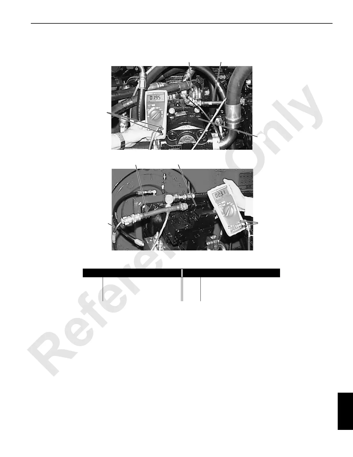
Test 13 – Testing the Pump EDC and Motor PCP
Testing a pump EDC or motor PCP requires a standard test
adapter (can be ordered from the Manitowoc Crane Care
Lattice Team) and a digital multi-meter. To test a pump
function:
• Disconnect the PC input cable from the pump EDC to be
tested.
• Connect the double-ended test adapter EDC.
• Leave the PC end of test plug disconnected.
• Set digital multi-meter for testing resistance.
• Connect white (positive) and black (negative) wires from
adapter cable to digital multi-meter jacks.
• Check that EDC resistance is between 17 and 19 ohms.
Leave test adapter installed at the pump EDC:
• Set the digital multi-meter for testing volts DC.
• Connect the PC input cable to PC end of test adapter.
• With engine running, slowly enable test system control
handle.
• Check that the range of voltage change is between 0
and +/-2.35 volts DC.
• Load current can be measured by connecting red and
white wires from adapter cable to digital multi-meter
jacks.
To test motor function, remove the PC input line from the
motor PCP and connect the test adapter. Perform the
resistance and voltage tests as described for pump EDC.
Motor PCP coil resistance should be between 23 to 26 ohms.
The voltage should be between 0 and 1.96 volts DC.
Item
Description
Item
Description
1 PC Input Cable 4 Test Adapter
2 Adapter Cable Connections 5 Motor PCP
3 Pump EDC
3
P1597
P1598
Motor
Pump
41
4
2
5
1
2

 Loading...


