ELECTRIC SYSTEM 999 SERVICE/MAINTENANCE MANUAL
3-42
Published 05-16-17, Control # 233-03
CPU EPROM REPLACEMENT
The central processing unit (CPU) in current production
programmable controllers — to include cranes with a Tier 4
Final engine — no longer has eproms (computer chips).
For information on updating crane software, contact your
Manitowoc dealer or the Manitowoc Crane Lattice Team.
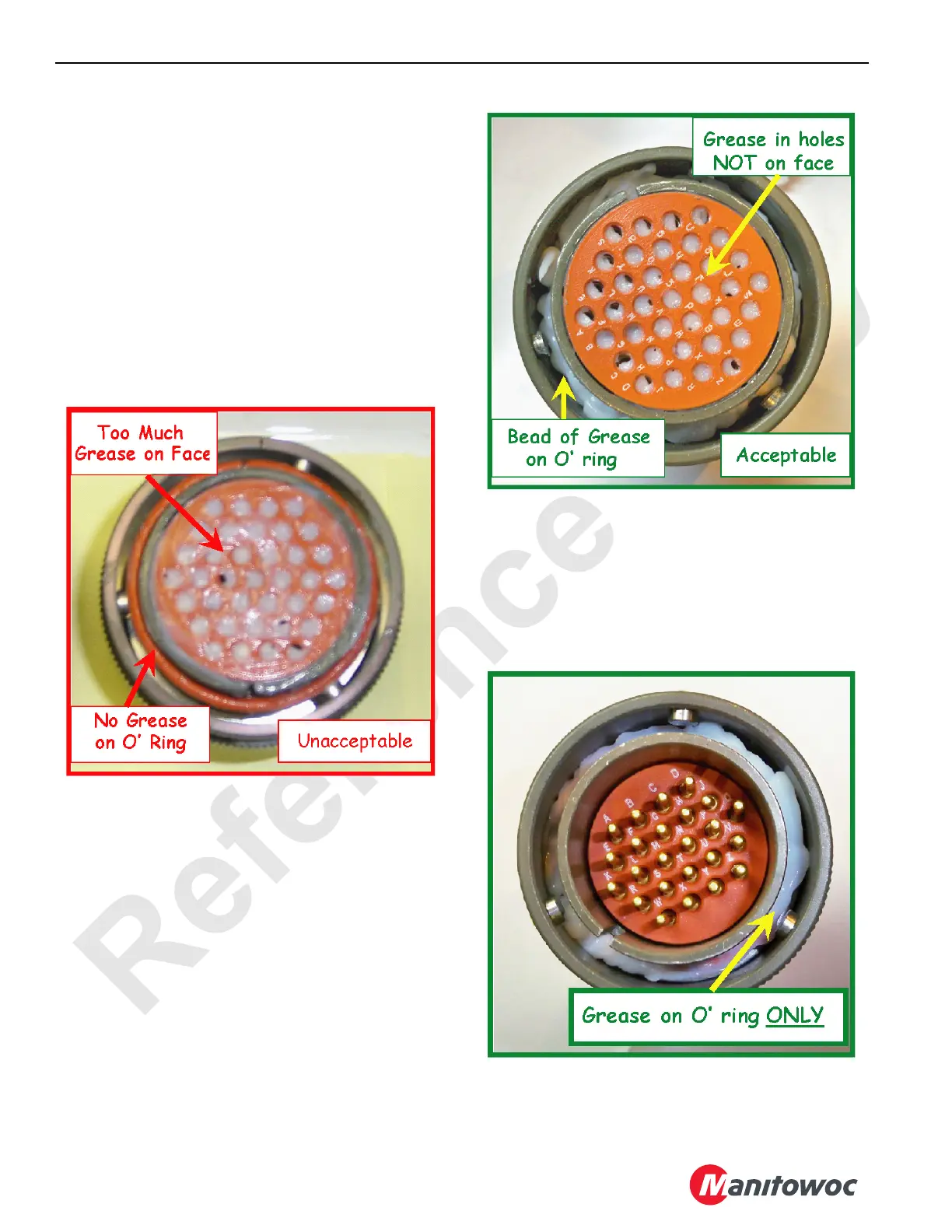
DIELECTRIC GREASE
The following figures show the proper application of
dielectric grease on J-tech type connectors.
Dielectric grease is need when assembling J-tech type
connectors. A bead of grease needs to be applied on O-ring
and face of the socket (female) connector and only on the
O-ring for a pin (male) connector.
The size of the grease bead on the O-ring is as follows:
• On a 3-pin connector a 1/16 inch (1,5 mm) bead is
required.
• On a 24-pin connector a 1/8 inch (3 mm) bead is
required.
• On a 37-pin connector a 3/16 inch (5 mm) bead is
required.
Place a small amount of grease on your finger for the
application on the connector’s face. Wipe your finger across
the face leaving grease inside the socket holes and less than
0.001 inch (0,025 mm) on the connector’s face. This helps
assure that water will be kept out of the connectors and keep
the pins from fretting.

 Loading...


