INTRODUCTION 999 SERVICE/MAINTENANCE MANUAL
1-4
Published 05-16-17, Control # 233-03
CRANE OPERATION
Operating System
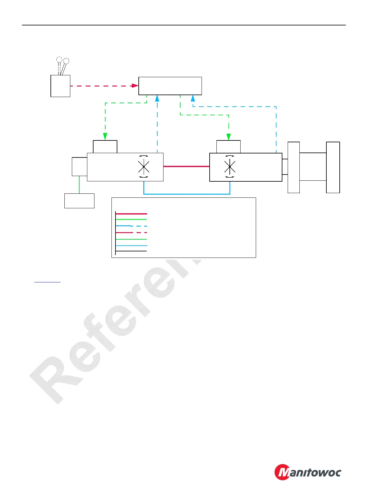
See Figure 1-1
The Model 999 operating system is an EPIC
®
(Electrical
Processed Independent Control). With this PC
(Programmable Controller) the independently powered
pumps and motors are controlled through operator
commands and control handles. The PC compares control
handle commands with monitored information from system
sensors. Crane information is displayed on a digital display
screen in operator's cab.
A diesel engine provides power to drive system pumps
through a gearbox.
In a closed-loop hydraulic system, high-pressure hydraulic
fluid from the system pump drives a hydraulic motor.
Pressure develops within the closed-loop system while
resistance of the load on motor is overcome. When
movement begins, pump volume displacement maintains
motor speed. Low-pressure side hydraulic fluid from motor
returns directly to pump input. The crane closed loop
systems are swing, right travel, left travel, boom hoist, front
drum, rear drum, and auxiliary drum.
NOTE: In this manual, a hydraulic system that is “open”
means fluid can flow in the circuit. In this manual,
each hydraulic solenoid valve is assigned an HS
(hydraulic solenoid) number. The HS numbers
identify actual hydraulic solenoid valves on the
crane for training proposes only.
Hydraulic Components
See Hydraulic Schematic drawing at end of Section 2.
Hydraulic Tank
Hydraulic tank has a fill cap, separate breather, suction filter,
diffuser filter, high and low level sight gauges, vacuum,
temperature, and level sensors.
The tank has two sections: a suction section and a return
section. The suction section 100-mesh (150 micron) strainer
has a 3 psi (0.2 bar) bypass that allows flow around it if it
becomes plugged. A diffuser filter inside tank return line
reduces turbulence created by fluid returning to tank.
Tank hydraulic filters remove contaminants from fluid.
NOTE: System filtration does not transform deteriorated
fluid into purified quality fluid. Factors affecting
service life of hydraulic fluid include high operating
FIGURE 1-1
Control Signal
(Pump Stroke)
Control
Handle
Pressure
Feedback
Motor Speed
Feedback
Programmable Controller
Handle
Command
Signal
Swashplate
Position
Control Signal
(Motor Stroke)
Hydraulic
Motor
Suction
Manifold
Charge
Pump
High Pressure
Side
Low Pressure Side
Hydraulic
Piping
Electronic
Displacement
Control (EDC)
Pressure
Control Pilot
(PCP)
Hydraulic
Pump
Drum
Line Legend
High-pressure Hydraulic, Positive Electrical
Negative Electrical (Ground)
Low-pressure Hydraulic, Signal Electrical
Control or Pilot Pressure Hydraulic
Hydraulic Suction
Case Return Pressure Hydraulic
Not Active Line or Circuit
999CSM1-100

 Loading...


