Manitowoc Published 05-16-17, Control # 233-03 3-39
999 SERVICE/MAINTENANCE MANUAL ELECTRIC SYSTEM
Bank 9**
1
2
4
8
16
32
64
128
Block Up Limit (Boom Top)
Block Up Limit (Boom Top)
Jib Minimum Down Working Limit
Jib Maximum Up Working Limit
Jib Maximum Up Stop
Block Up Limit (Luffing Jib/Fixed Jib Top)
Block Up Limit (Luffing Jib Top)
Block Up Limit (Fixed Jib on Luffing Jib Top
)
*Binary
** Bank 9 inputs are from RIN computer, not system
computer.
Table 3-8 D2 (Crane Digital Inputs)
Identifier* Component
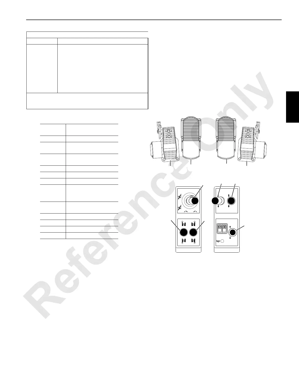
Handle/Pedal Identification
* Activated only in luffing jib mode.
** Special handle arrangement activated
only in luffing jib mode.
Handle
Number
Crane
(All Modes)
1 Front Load Drum
2
Rear Load Drum or
Luffing Hoist*
3
Boom Hoist or
Luffing Hoist**
4Swing
5 Right Crawler
6 Left Crawler
7
Auxiliary Load Drum
(in butt) or
Luffing Hoist**
Pedal
Number
1 Right Crawler
2 Left Crawler
3 Front Drum Brake
4 Rear Drum Brake
FIGURE 3-15
A817
3
2
1
4
5
7
6
3
1
2
4

 Loading...


