ELECTRIC SYSTEM RT540E SERVICE MANUAL
3-2 Published 4-20-2015, Control # 502-01
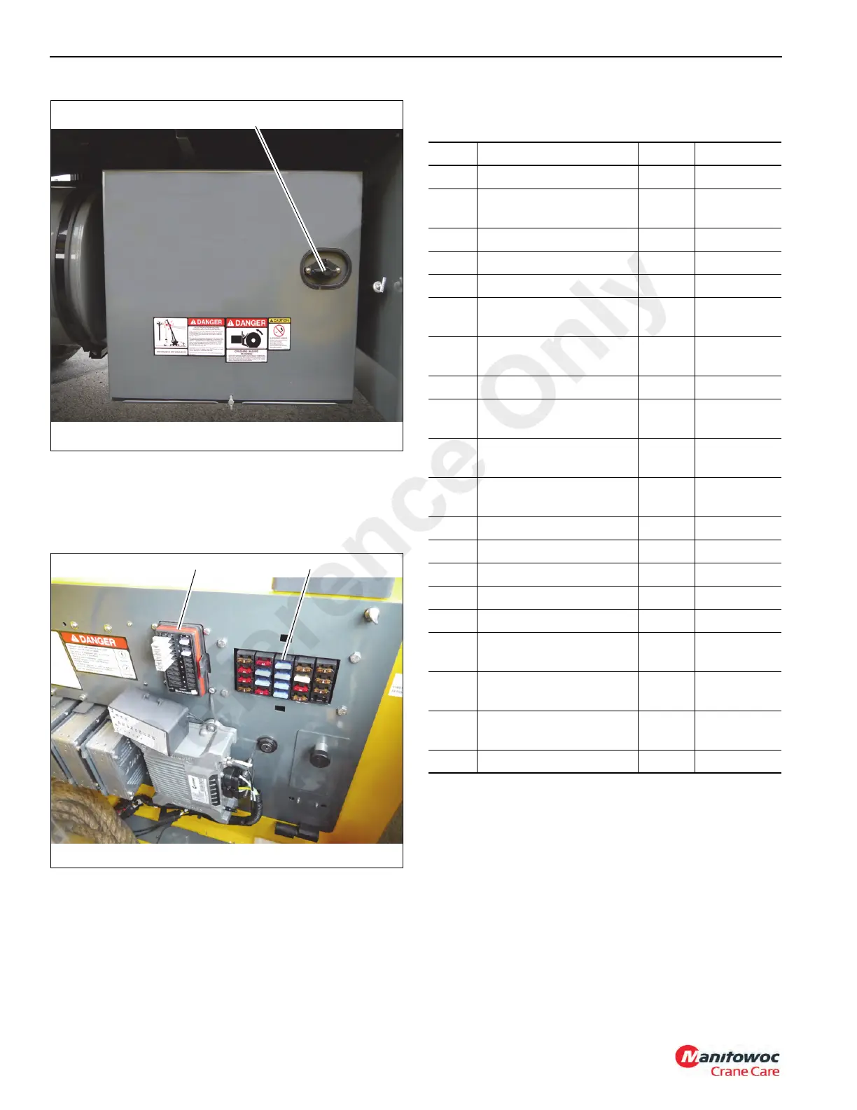
Fuse Panel
Fuses are located behind the seat in the cab (1) (Figure 3-3).
In the battery box fuse panel (3) (Figure 3-4) and in the
battery box (4).
The following fuse assignments apply:
Table 3-1: Superstructure Cab Power Panel
Fuse Protects Amps Location
F1 Dome Light 5 (Figure 3-3)
F2
ACC Power Outlet/
Heater Motor
10 (Figure 3-3)
F3 Work Lights 10 (Figure 3-3)
F4 Steering Column Power 5 (Figure 3-3)
F5 Key Switch Power 10 (Figure 3-3)
F6
Turntable Module
Battery Power
15 (Figure 3-3)
F7
Master/Cab Slave
Module Battery Power
15 (Figure 3-3)
F8 Skylight Wiper 10 (Figure 3-3)
F9
Turntable Option Module
Battery Power
15 (Figure 3-3)
F10
Turntable Option Module
Battery Power
15 (Figure 3-3)
F11
Turntable Module
Battery Power
15 (Figure 3-3)
F12 Diagnostic Tool Power 15 (Figure 3-3)
F13 Accessory Lights Power 15 (Figure 3-3)
F14 Oil Cooler 25 (Figure 3-3)
F15 Heater/AC Panel 10 (Figure 3-3)
F16 Circulating Fan 5 (Figure 3-3)
F17
Joystick/Jogdial/
Operator Display Power
5 (Figure 3-3)
F18
Master/Cab Slave
Module PCB Power
5 (Figure 3-3)
F19
Turntable Module PCB
Power
5 (Figure 3-3)
F20 Spare (Figure 3-3)
1
Reference Only

 Loading...


