HOIST AND COUNTERWEIGHT RT540E SERVICE MANUAL
5-6 Published 4-20-2015, Control # 502-01
more dangerous failure. Early detection of accelerated
component wear allows the scheduling of corrective
maintenance.
Prepare the hoist by cleaning the drain plug area and drain
extension tube in order to obtain an uncontaminated
sample. Operate the hoist in both directions for one or two
minutes to thoroughly mix the gear oil then take the sample
from the midstream flow of the oil to obtain an accurate
representation of the oil condition. After taking the oil sample
continue with the oil change or refill the hoist gear cavity to
the proper level with recommended lubricant. Iron
contaminant levels will be on the high side of “normal”
during initial break-in.
Equally important as the level of contamination is the
change in level of contamination. An effective oil analysis
program should provide the technician with a view of the
progression of wear or a trend. If a sample shows a sudden
rise in contaminant level action should be taken to
determine what has changed.
NOTE: Oil analysis alone cannot detect nor warn against a
fatigue failure.
BRAKE TEST PROCEDURE FOR HP15C-
17G, HO30A-19G, HP35-26G HOISTS
All of the above model planetary hoists have a spring
applied, hydraulically released, multiple disc brake inside
the hoist housing. This brake holds a suspended load when
the directional control valve is in neutral, or when hydraulic
power is lost. An over-running brake clutch assembly
permits the power train and drum to rotate in the direction to
lift a load, while the brake remains fully applied. A load
cannot be lowered, however, without applying hydraulic
pressure to the release port and releasing the brake.
Brake Test Procedure (To be performed with
no load on the hoist)
• Remove and cap or plug the brake release line from
fitting in the hoist brake release port.
• With the hydraulic power unit running, move the
directional control valve handle slowly to the full open,
lowering position.
• Increase the engine speed, if necessary, to bring system
pressure up to the relief valve setting. The hoist drum
should remain stationary
• If the hoist drum rotates, the hoist should be
disassembled and the brake components should be
examined for wear. In addition, the brake springs should
be measured for the correct free length in those hoist
using helical compression springs.
• Replace any parts showing excessive wear and any
spring whose length is shorter than the minimum shown
in the applicable hoist Service Manual.
• Reassemble the brake and hoist, then repeat the above
steps.
• When testing is complete, reattach the brake release
line to the brake release port.
Contact CraneCARE with any questions
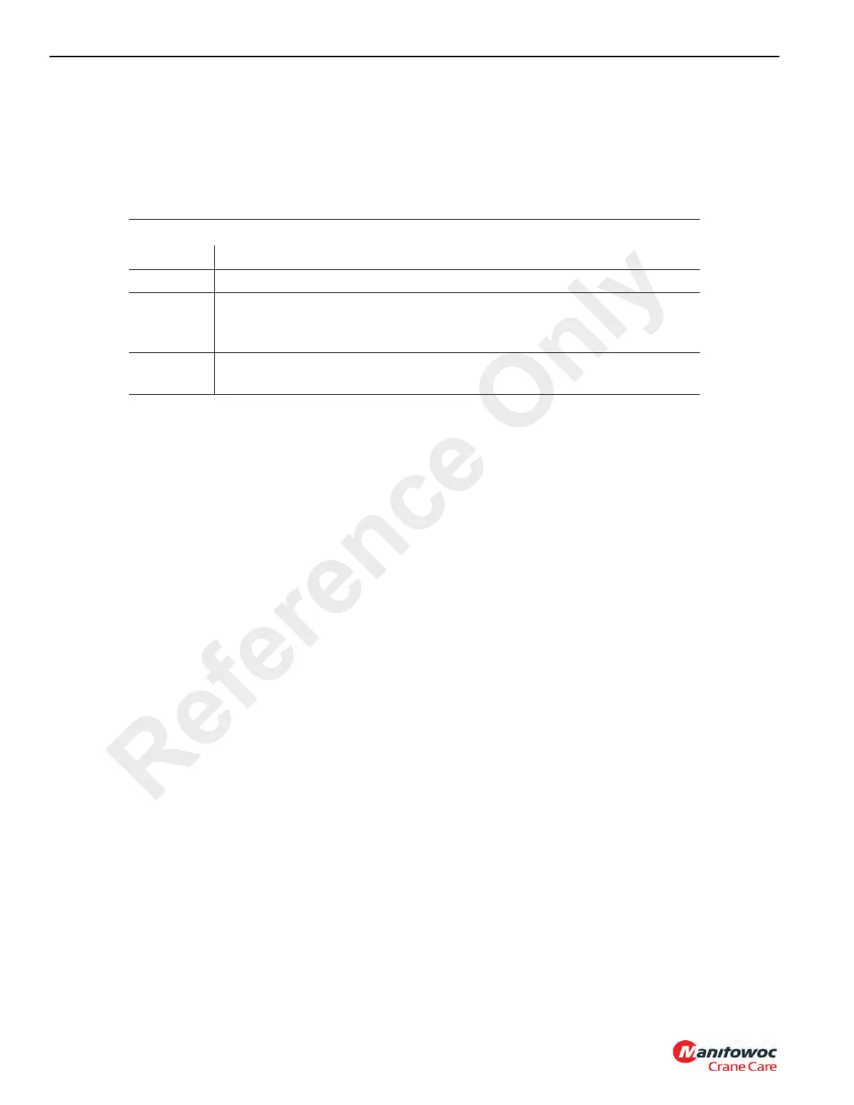
General guidelines for iron contaminant level
PPM Condition of Oil
100-500 Normal - Acceptable level; little significant contamination
500-800
Caution - Abnormal sample. Change oil and retake sample after 50 hours of
operation. If second sample is above 500 ppm, remove hoist from service and
perform tear-down inspection to determine source of contamination.
Over 800
Unacceptable - Remove hoist from service and perform tear-down inspection to
determine the source of contamination.
Reference Only

 Loading...


