Published 4-20-2015, Control # 502-01 2-35
RT540E SERVICE MANUAL HYDRAULIC SYSTEM
STEERING CONTROL VALVE
Description
The steering control unit (Figure 2-17) controls hydraulic flow
to the front steering cylinders. It is located on the steering
column of the cab.
Both work ports are connected to the rod side of one steer
cylinder and to the piston side of the other steer cylinder. A
steering wheel input will connect the load sense port #5 to
the steering cylinder load demand by way of the steer priority
valve located in the swing/steer manifold.
Displacement of the valve is 315 cm³ (19.22 in³).
Maintenance
Removal
1. Tag and disconnect the electrical connector to the valve.
2. Tag and disconnect the hydraulic hoses from the valve.
Cap or plug the lines and ports.
3. Remove the capscrews and washers and remove the
valve from the steering column.
Installation
1. Secure the valve to the steering column and secure with
the capscrews and washers. Torque the capscrews see
Fasteners and Torque Values, page 1-11.
2. Connect the hydraulic hoses to the ports on the valve as
tagged during removal.
3. Connect the electrical connector to the valve as tagged
during removal.
4. Verify proper operation of the valve.
5. Check valve and hydraulic connections for leaks. Make
repairs as needed.
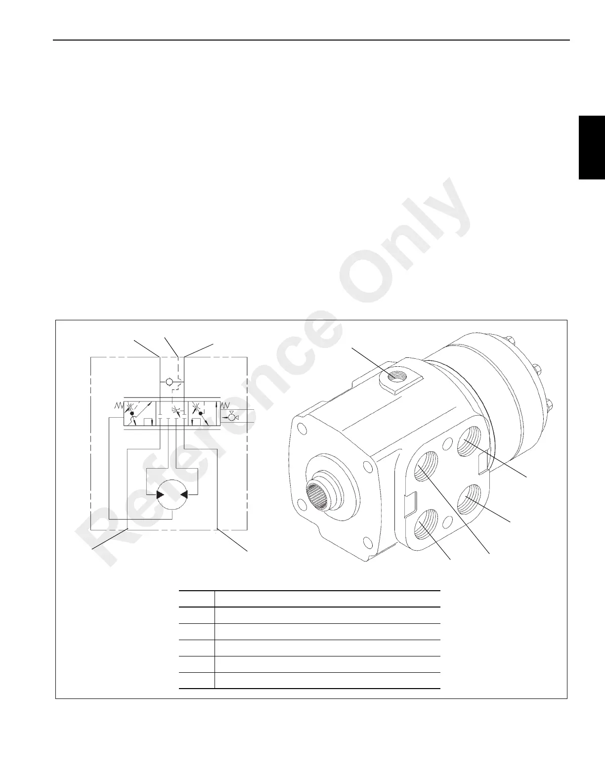
FIGURE 2-17
1
2
1
3
2
4
5
5
3
4
Item Description
1 Port T - Tank Port - To Swivel Port 4
2 Port P - Pressure From Port 1B- Accessory Manifold
3 Port R - To Right Front Steer Cylinder
4 Port L - To Left Front Steer Cylinder
5 Port LS - From Port 1A - Accessory Manifold
Valve Hydraulic Schematic
6747-2
6747
Reference Only

 Loading...


