UNDERCARRIAGE RT540E SERVICE MANUAL
8-24 Published 4-20-2015, Control # 502-01
Caliper
1. Position the caliper housing on the mounting bracket. If
shims where used, place them as marker during
removal.
2. Secure the caliper housing with the bolts and tighten
them to 678 to 813 Nm (500 to 600 lb-ft).
3. Install the linings. Refer to INSTALLATION - Linings.
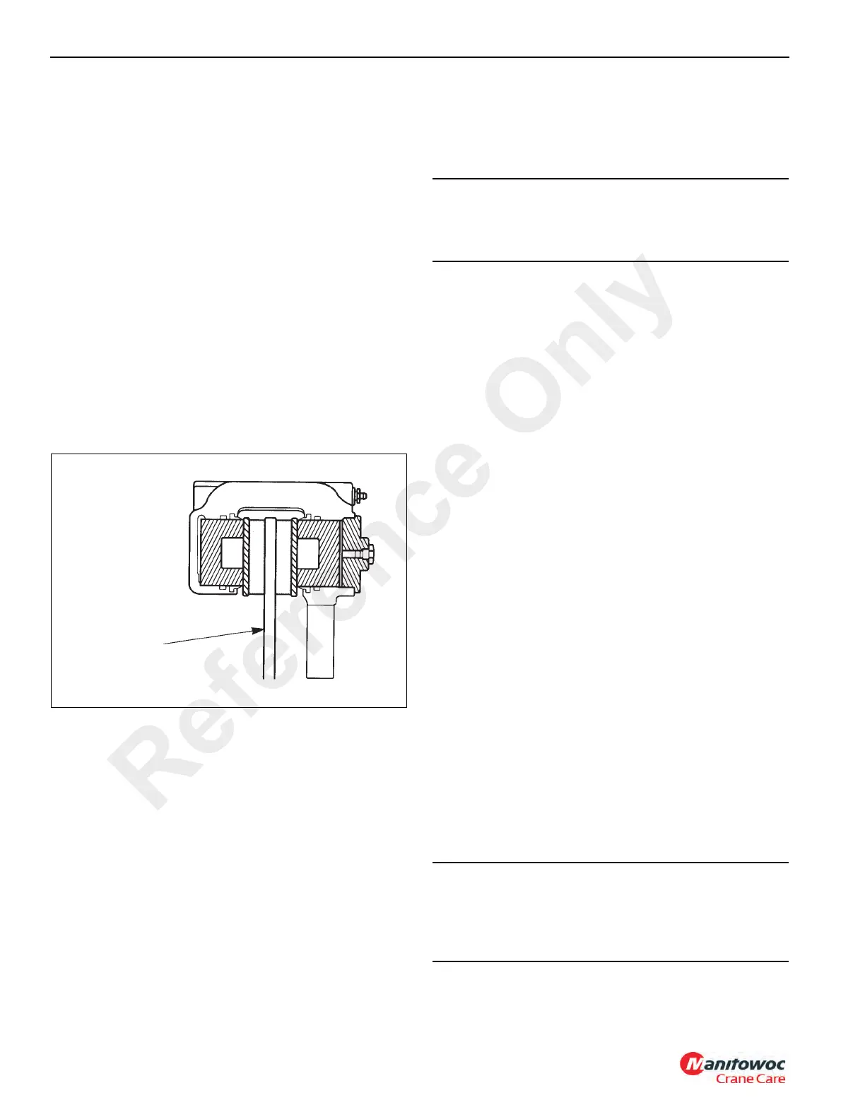
4. Ensure the housing is installed correctly on the mounting
bracket. The disc must be within ±1.5 mm (±0.06 in) of
being centered between the lining end plates.
a. To increase outboard clearance and decrease
inboard clearance, install a shim either between the
housing and mounting bracket or between the hub
and disc.
b. The shims must be steel, ground flat, and parallel
and must cover the entire mounting surface of the
hub or housing. The linings must move freely in the
housing and between the end plates (Figure 8-27).
5. Connect the hydraulic brake line to the inlet fitting.
6. Bleed the brake system.
7. Apply and release the brakes three times to ensure the
caliper operates correctly. Check for fluid leaks. Ensure
the linings move freely.
PARKING BRAKE ACTUATOR
Description
The spring-applied, hydraulically-released parking brake
actuator is located on the transmission and is used to apply
and release the parking brake.
Maintenance
Removal
1. Chock the wheels to prevent crane movement.
2. Start the engine, ensure the transmission is in neutral,
and position the Park Brake switch to Off. This will
pressurize the brake actuator to release the tension on
the brake linkage. Engine must remain running.
3. Remove the capscrews securing actuator to the brake
caliper. Slide the actuator off the actuator rod.
4. Position the Park Brake switch to On (press top of
switch) and shut down the engine.
5. Disconnect the hydraulic line from the brake actuator,
then cap or plug all openings.
Installation
NOTE: Mount brake so that the linings are parallel with the
disc within 0.381 mm (0.015 in). Disc is to be
located the proper distance from the mounting
surface per assembly drawing.
1. Slide brake over disc and into mounting position.
2. Start hex mounting bolts into mounting surface far
enough to just support the brake.
3. Remove plug, loosen the coupling nut and then tighten
socket setscrew until linings are clamped to the disc.
This locates and holds the brake in the proper position to
set the hex mounting bolts and hex nuts.
4. Tighten hex mounting bolts until they make contact with
the urethane springs, then tighten 4 flats approximately
1.778 mm (0.07 in) more. This puts the proper amount
of pre-load on the urethane springs.
5. Tighten jam nut/sleeves against mounting surface and
torque 271 Nm (200 lb-ft).
Disc Centered
Between Linings
FIGURE 8-27
CAUTION
Do not exceed 1861.5 kPa/18.6 bar (270 psi) hydraulic
pressure to avoid damage to the brake. 1172.1kPa/11 bar
(170 psi) is required to fully release the brake.
CAUTION
Brake linings are susceptible to contamination. When
installing or servicing brakes, keep all oil and fluids away
from linings. Poor brake performance may result if linings
are contaminated.
Reference Only

 Loading...


