Published 4-20-2015, Control # 502-01 8-23
RT540E SERVICE MANUAL UNDERCARRIAGE
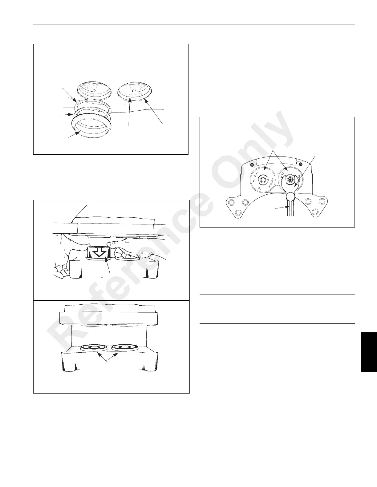
4. Install the pistons in the housing. Push the pistons in
from the lining side of the housing. Ensure the pistons
are straight in the bores. Push each piston into the bore
until the top of the piston is even with the top of the dust
seal (Figure 8-25).
5. Install a new o-ring in the groove of the cylinder cap.
Ensure the o-ring is not cut by the threads on the
cylinder cap.
NOTE: Apply extra grease on o-ring before installing
cylinder caps. this will keep o-ring from catching on
threads as cylinder cap is threaded into housing.
6. Install the cylinder caps in the caliper housing. Tighten
the cylinder caps to 102 Nm (75 lb-ft) minimum as
shown in (Figure 8-26).
7. Install the bleeder screws in the housing. Tighten to 11.3
to 13.6 Nm (100 to 120 lb-in).
8. Install the o-ring and the inlet fitting in the cylinder cap.
Installation
Linings
1. Install the linings in the caliper housing.
2. Position the end plates on the housing and secure with
bolts. Apply Loctite 271 or equivalent to the bolt threads.
Tighten the bolts to 224 to 285 Nm (165 to 210 lb-ft).
3. Ensure the linings move freely in the housing.
4. Bleed the brake system.
5. Apply and release the brakes three times to ensure the
caliper operates correctly. Check for fluid leaks. Ensure
the linings move freely.
Backup Ring
and O-Ring
Groove
Dust Seal
Groove
O-Ring
Backup
Ring
Dust Seal
FIGURE 8-24
O-Ring-
Install Toward
Outboard End of Bore
Backup Ring -
Install Toward Lining
Side of Bore O-Ring
Piston - - Use
Equal Pressure to
Push Pedal into Bore
When Correctly
Installed the End of the
Piston is Even with the
Top of the Dust Seal
FIGURE 8-25
CAUTION
Always replace both linings. If only one lining is replaced,
possible disc damage can occur.
Torque
Wrench
Cylinder Cap - -
Tighten to 100 Nm
(75 pounds-foot)
Minimum
1.25 Inch
Crow’s Foot
Wrench
FIGURE 8-26
Reference Only

 Loading...


