BOOM RT540E SERVICE MANUAL
4-8 Published 4-20-2015, Control # 502-01
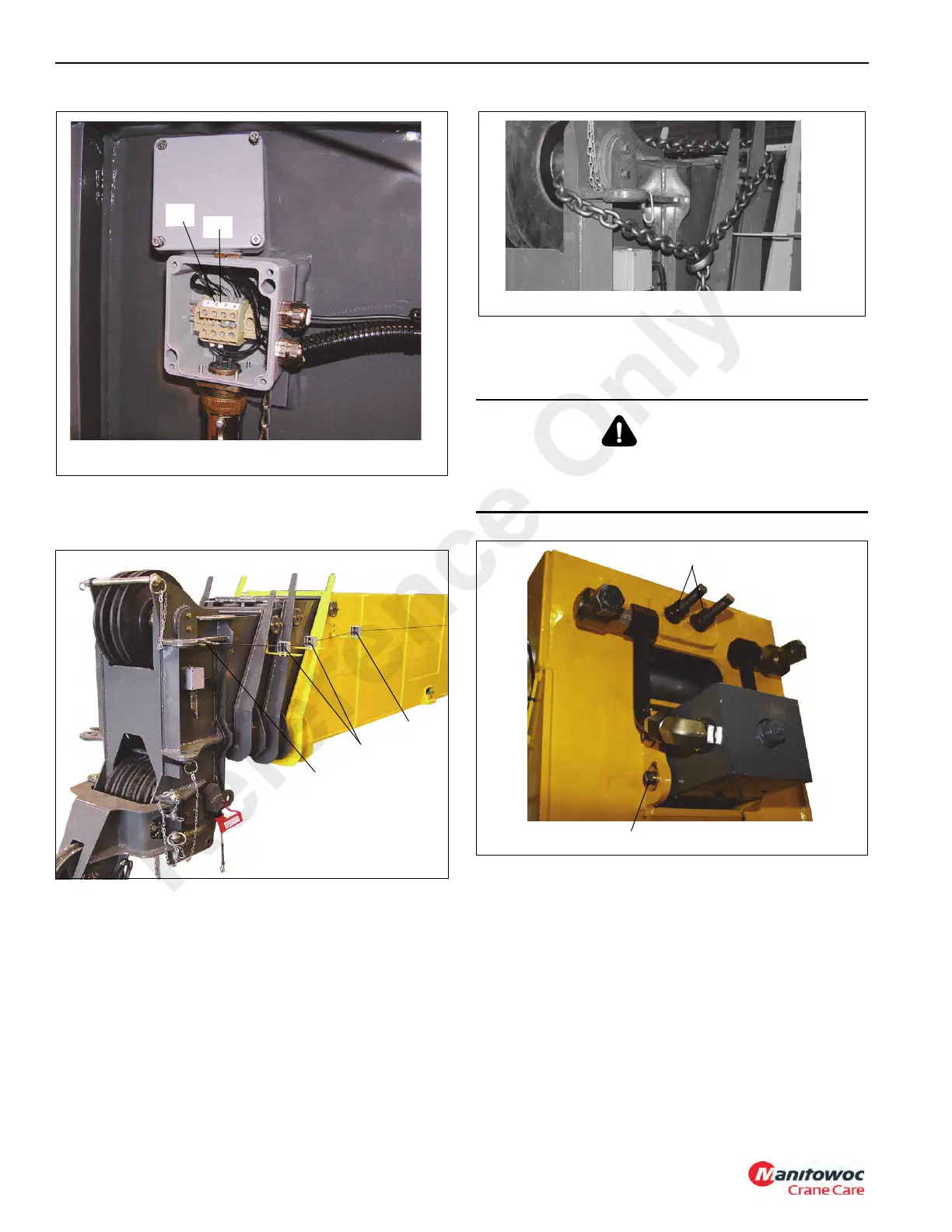
3. Disconnect cable from the Fly section (Figure 4-8, 3)
and feed cable through cable guides (Figure 4-8, 1) and
attach to the Base section cable guide (Figure 4-8, 2).
4. Chain the Fly, Outer Mid and Inner Mid sections
together. This will prevent the inadvertent or unexpected
extension of these sections during the boom
disassembly. Figure 4-9
5. Remove the bolts and washers securing the telescope
cylinder outer rod (Figure 4-10, 1) to the rear of the base
section.
6. Remove the nuts and washers securing the
synchronizing cable (Figure 4-10, 2) ends to the base
section.
Remove the Base Section
Do not attempt to work on the boom without experienced
supervision
CAUTION
Use extreme caution during piston and rod tube assembly
removal. The telescopic cylinder will still be under
hydraulic pressure due to the holding valve.
Reference Only

 Loading...


