Published 4-20-2015, Control # 502-01 4-15
RT540E SERVICE MANUAL BOOM
NOTE: Pull the extend cable along with the telescope
cylinder (Figure 4-31). Failure to do so will cause
binding and jamming of the cables in the fly
section.
3. Remove the two bolts securing the extend cable keeper
plate (Figure 4-32, 1) to the rear of the fly. Remove the
keeper plate and remove the five extend cable ends
from the slots in the fly.
4. After supporting the weight of the tele cylinder, remove
the two bolts securing the cylinder foot weldment
(Figure 4-33, 1) to the telescope cylinder (Figure 4-33,
2). Remove the foot weldment.
5. Completely remove the Tele Cylinder from the Fly
Section.
6. Remove bottom and lower rear side wear pads and
shims if they are to be replaced. Note location of shims
for installation.
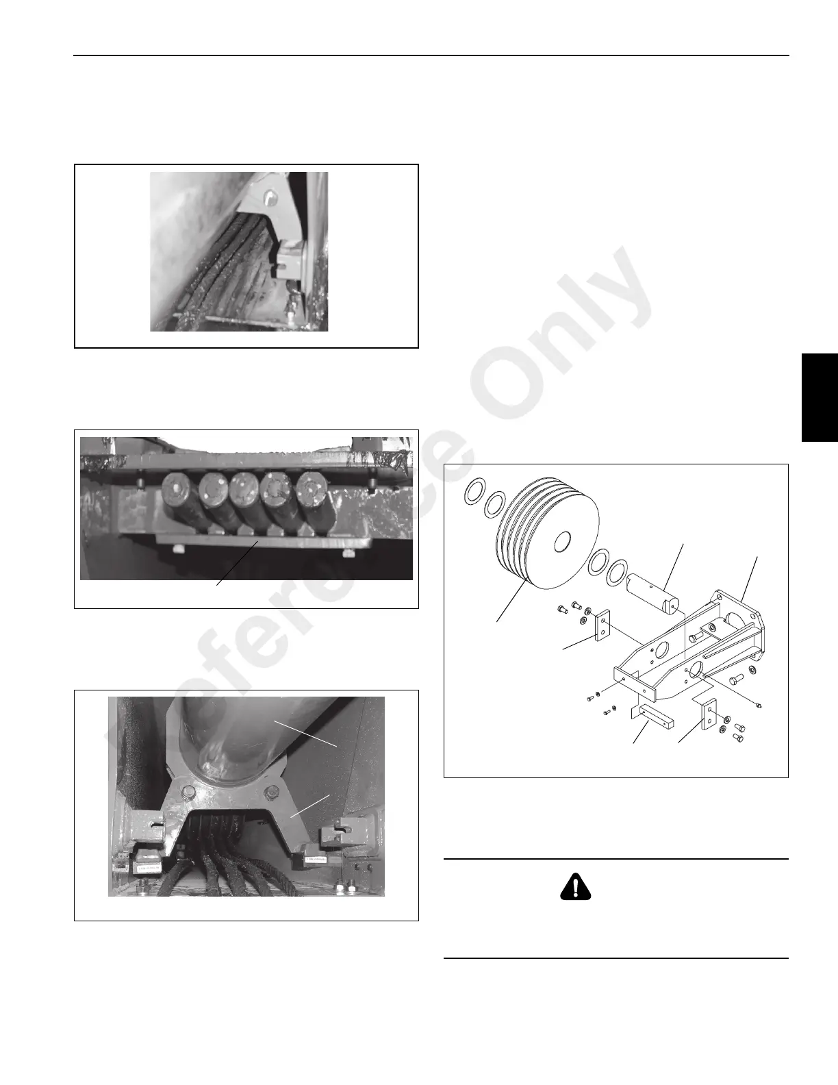
Extend Cable Sheave Removal
1. Remove the bolts holding the Cable Retainer
(Figure 4-34, 1) to Sheave Mount (Figure 4-34, 2).
Remove the Retainer.
NOTE: If the extend cables are to be reused, be sure that
they are marked before removal to aid in
reassembly.
2. Remove the five extend cables.
NOTE: The boom nose sheave weighs approximately 17.3
kg (38 lb).
3. Remove the sheave shaft retainer plates (Figure 4-34,
3) from left and right side of the sheave mount.
4. Carefully pull the sheave shaft (Figure 4-34, 4) from the
assembly, removing the spacers, and sheave
(Figure 4-34, 5). Note the quantity of the spacers for
installation.
BOOM NOSE SHEAVES
Do not attempt to work on the boom without experienced
supervision.
DANGER
To prevent serious injury or death, always wear personal
protective equipment; i.e., a hard hat, eye protection,
gloves and metatarsal boots.
Reference Only

 Loading...


