HYDRAULIC SYSTEM RT540E SERVICE MANUAL
2-36 Published 4-20-2015, Control # 502-01
TANDEM BRAKE VALVE WITH TREADLE
PEDAL
Description
The tandem brake valve with treadle pedal (Figure 2-18) is
located on the floor of the cab. The tandem brake valve
provides split system braking for the primary (front) brakes
and the secondary (rear) brakes.
The valve modulates the output pressure 10,342 kPa/103.4
bar (1500 psi) to the brake actuators. The valve is
mechanically actuated by a treadle pedal (Figure 2-18). The
direct acting spool provides a pedal feel which accurately
represents the brake pressure, similar to automotive style
pedal feedback as the brake pedal pressure increases, the
pedal effort increases proportionally. As the pedal is initially
actuated, the tank ports are closed off from the brake ports.
With further application of the pedal, the pressure ports are
opened to the brake ports until the pedal actuation force and
the hydraulic pressure force are balanced.
Also when the pedal is actuated, a pressure switch located
off a tee in port F2 provides an electrical signal for brake
lights. When the pedal is released, the valve and the pedal
return to the non-applied position. In normal operation, the
secondary system is piloted from the primary section
providing pressure to both systems.
The tandem brake valve consists of a tandem valve body, a
closed center spool, a treadle pedal and a mechanical spring
assembly to limit the output pressure to the brake actuators
to 10,342 kPa/103.4 bar (1500 psi).
Maintenance
Removal
1. Tag and disconnect the electrical connector to the valve.
2. Tag and disconnect the hydraulic hoses from the valve.
Cap or plug the lines and ports.
3. Remove the capscrews, lockwashers, flatwashers and
nuts securing the valve to the cab Floor. Remove the
valve.
Installation
1. Secure the valve to the cab floor with the capscrews,
lockwashers, flatwashers and nuts. Torque the
capscrews 10 to 11 Nm (7.4 to 8.1 pounds-foot).
2. Connect the hydraulic hoses to the ports on the valve as
tagged during removal.
3. Connect the electrical connector to the valve as tagged
during removal.
4. Start the engine and check valve and hoses for leaks.
Make repairs as needed.
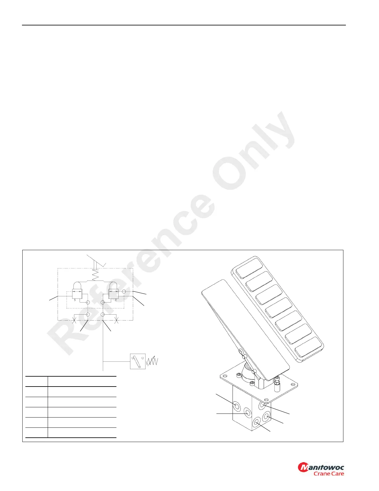
Valve Hydraulic Schematic
FIGURE 2-18
Item Description
1 Pressure Port P1
2 Pressure Port P2
3 Port F1- Front Brakes
4 Port F2 - Rear Brakes
5Port T - Tank
2
1
4
3
5
2
3
4
5
1
6745-1
6745-2
Reference Only

 Loading...


