Published 4-20-2015, Control # 502-01 4-31
RT540E SERVICE MANUAL BOOM
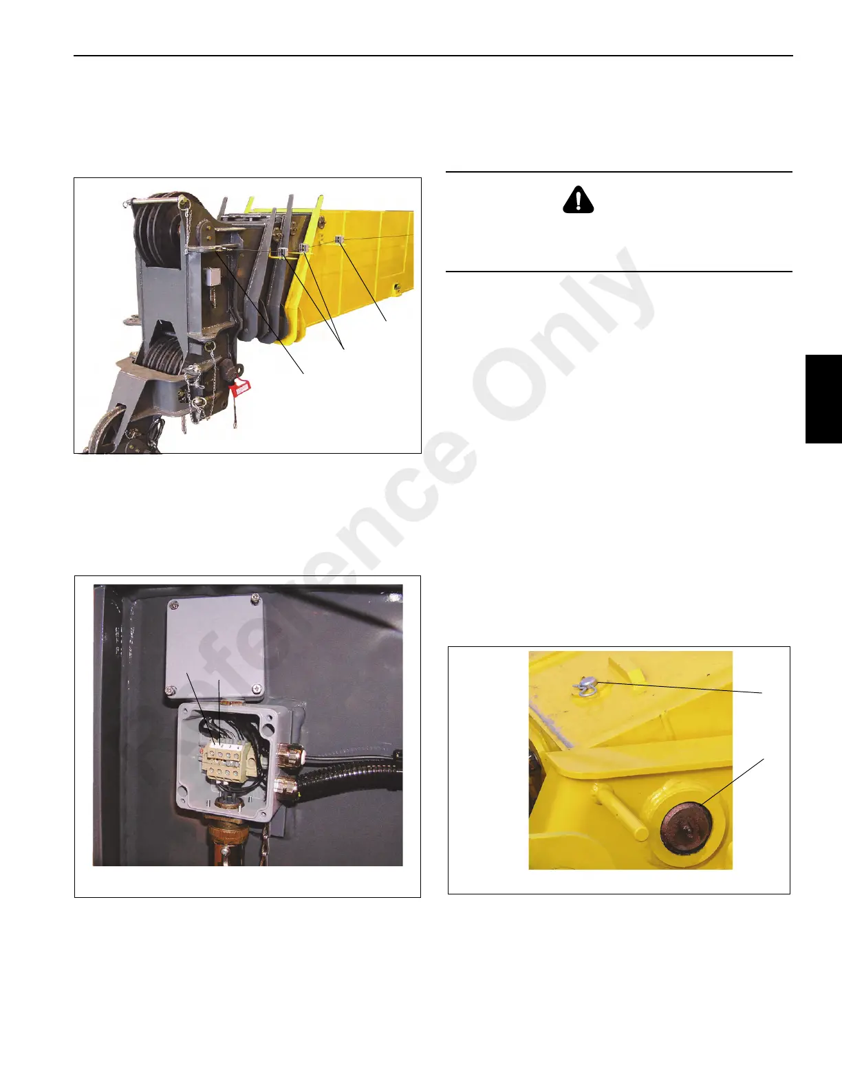
12. Disconnect RCL, A2B/Cable that was attached to the
Base section cable guide (Figure 4-89, 1) in the removal
of the boom and feed cable through the Inner and Outer
Mid section cable guides (Figure 4-89, 2) and through
the Fly section cable guide (Figure 4-89, 3).
13. Remove the RCL, A2B/Cable from boom nose.
c. Connect cable connector to side of junction box.
d. Connect “SHD” wire (Figure 4-90, 1) to terminal 1
and “CORE” wire (Figure 4-90, 2) to terminal 2.
a. Replace cover to junction box.
FINAL BOOM ASSEMBLY
Do not attempt to work on the boom without experienced
supervision.
NOTE: The boom may be disassembled with the base
section left on the crane if repair of the base section
is not necessary.
NOTE: The complete boom assembly weighs
approximately 5800 kg (12,740 lb) without the
swingaway boom extension attached. Removal of
the swingaway boom extension will simplify boom
removal.
1. Attach a lifting device to the boom to provide for equal
weight distribution.
2. Raise the boom off of the blocking or cribbing high
enough to clear the crane and lower to crane
superstructure assembly.
3. Align the boom with the superstructure assembly.
4. Insert the boom pivot shaft and thrust washers through
superstructure assembly and boom.
5. Insert the clip pin and retaining pin (Figure 4-6, 1)
securing the boom pivot shaft (Figure 4-6, 2) on the
boom to the superstructure assembly.
6. Install the grease fittings on the pivot shaft and add
grease per requirements in LUBRICATION (pg 9-1).
7. Remove the hard cap or plugs in the hydraulic lines and
openings and connect the hydraulic lines to the
telescope cylinder.
DANGER
To prevent serious injury or death, always wear personal
protective equipment; i.e., a hard hat, eye protection,
gloves and metatarsal boots.
Reference Only

 Loading...


