BOOM RT540E SERVICE MANUAL
4-30 Published 4-20-2015, Control # 502-01
7. Carefully guide the port block into the anchor weldment.
8. Insert two tele rod end pins. Secure both ends of each
pin with a flat washer, lock washer, and capscrew
(Figure 4-86).
NOTE: It may be necessary to gently pry the port block to
align the pin holes.
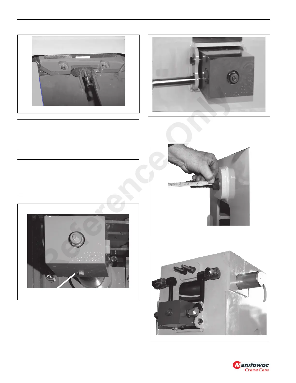
9. Connect Mid Syncro Cables to rear of Base section.
10. Adjust cable until there is 76mm (3 inch) of threads
showing past adjustment nut (Figure 4-87).
11. Plumb port block with tubing (Figure 4-88).
CAUTION
Ensure the Tele Cylinder Port Block is correctly positioned
before proceeding. The boom will not function properly if
the Port Block is not installed as shown in Figure 4-85.
CAUTION
There is less than 3mm of clearance between the sides of
the weldment and the port block during installation.
Remove any plugs/caps that may interfere with
installation.
Test Port
FIGURE 4-85
Test Port
Reference Only

 Loading...


