Published 4-20-2015, Control # 502-01 2-27
RT540E SERVICE MANUAL HYDRAULIC SYSTEM
VALVES
General
This subsection provides descriptive information for all the
hydraulic valves used on this crane. For a listing of all valves,
the circuit they are used in and their physical location, refer
to (Table 2-2). Refer to (Figure 2-14) for valve locations. The
description of each valve given here is for the valve itself. For
information on how each valve functions in the individual
circuits, refer to the description and operation procedures of
that circuit.
NOTE: On each valve illustration in this section, each item
number in table correlates to location on the valve,
and to the valve hydraulic schematic.
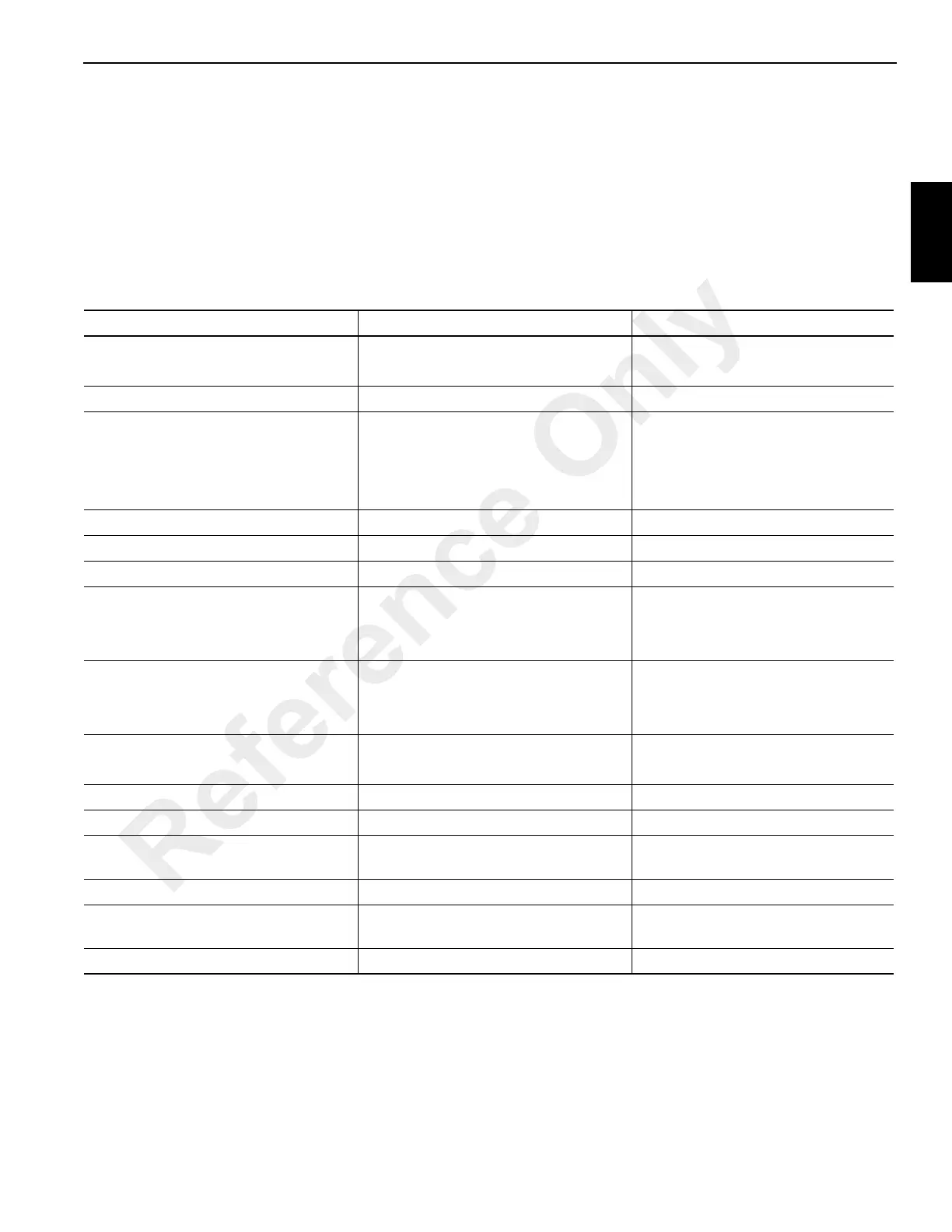
Table 2-2
Valve Usage Table
Valve Name Circuit Used In Physical Location
Directional Control Valves Boom Lift/Telescope(s)/Hoist(s)
Swing/Steer
Superstructure Right Side Plate
Superstructure Right Side Plate
Steering Control Valve Front Axle Steer Control Cab Steering Column
Front Steer/Swing/Accessory Manifold Front Axle Steer Supply
Swing Directional Control
Swing Brake Release
Pilot Supply
Superstructure Right Side Plate
Tandem Brake Valve with Treadle Service Brakes Cab Floor
Dual Accumulator Charging Valve Service Brakes Superstructure Left Side Plate
Accumulator(s) Service Brake Rear Superstructure
Holding Valves Boom Lift
Telescope (3)
Counterweight Removal (2)
Lift Cylinder (Bolt on Manifold)
Cylinder Port Blocks (Cartridge style)
Cylinder Port Blocks (Cartridge style)
Axle Lockout, Rear Steer and Oil
Cooler Fan Motor Control Manifold
Axle Lockout Control
Rear Steer Control
Oil Cooler Motor Control
Left Hand Carrier Frame Rail
Solenoid Valves:
Cross Axle Differential Lock Differential Lock (Optional) Carrier Inside Right Side Rail
Hoist Motor Control Valve Hoist(s) Both Hoists (see Hoist section)
Check Valves Return Circuit One in Parallel With Oil Cooler
Outrigger Control Manifold Outrigger On Front and Rear Face of Carrier
Frame Front and Rear Cross Member
Pilot Operated Check Valve Outrigger Port Block of each Jack Cylinder (4)
Cross Axle Differential Lock Valve Differential Lock (Optional) Carrier Bulkhead Plate Forward Of
The Engine
Range Shift and Parking Brake Valve Parking Brake Axle Disconnect Center of Rear Frame
Reference Only

 Loading...


