HOIST AND COUNTERWEIGHT RT540E SERVICE MANUAL
5-8 Published 4-20-2015, Control # 502-01
.
PISTON MOTOR AND CONTROL VALVE
Description
The piston motor is a bent axis, bidirectional, variable
displacement heavy-duty motor. The motor is bolted to the
hoist and is geared directly to the hoist planetary.
The motor control valve is bolted to the motor.
Maintenance
Removal
1. Thoroughly clean the external surfaces of the drum and
motor with steam or clean solvent and blow dry.
2. Tag and disconnect the hydraulic lines connected to the
hoist motor and the motor control valve.
3. Remove the capscrews and lockwashers that secures
the motor and motor control valve to the hoist.
NOTE: The HP15C-17G hoist motor weighs approximately
28 kg (62 lb).
4. Place the motor and motor control valve in a clean, dry
suitable work area.
Installation
NOTE: Care must be taken to assure the primary thrust
plate remains properly located in its counterbore
when the motor is re-installed. If the winch is
operated with the primary thrust plate wedged
between the primary gears and the planet carrier,
or with a thrust washer out of position severe
damage to internal winch components could result.
1. Install a new O-ring on the motor pilot then lubricate with
petroleum jelly or gear oil. Engage the motor shaft with
the brake clutch inner race and lower into place.
2. Apply Loctite No. 243 to the mounting bolts, and install
the bolts and lockwashers. Torque the bolts to 102 Nm
(75 lb-ft).
3. Connect the hydraulic lines as tagged during removal.
4. Fill the drum with oil. Refer to Section 9 - LUBRICATION
in this manual.
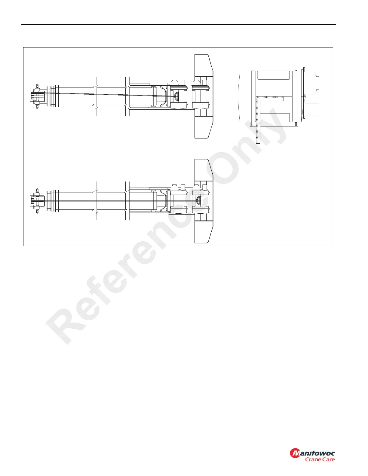
LOCATING CENTERLINE WITH
SQUARE
MAIN HOIST IS ALIGNED TO THE RIGHT HAND
SHEAVE
AUXILIARY HOIST IS ALIGNED TO THE CENTER
SHEAVE
FIGURE 5-2
6019
Reference Only

 Loading...


