Published 4-20-2015, Control # 502-01 7-5
RT540E SERVICE MANUAL POWER TRAIN
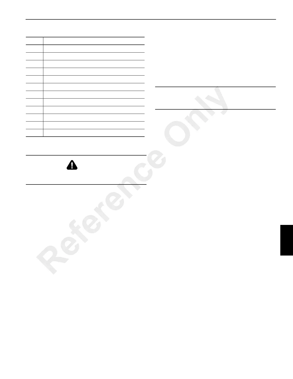
Figure 7-1 Item Numbers
Engine Installation
NOTE: Use the same grade hardware, torque values, and
Loctite that were used by the factory.
NOTE: Apply medium strength sealant (Loctite 243) to
engine attaching hardware.
1. With all components and fittings installed on the new
engine, lift the engine into the crane.
2. With the engine in position, install the mounting plate,
insulator, nuts, washers and capscrews and secure rear
of engine (Figure 7-1). Torque M16 grade 10.9
capscrews see Fasteners and Torque Values (pg 1-11).
3. At the front of the engine install the capscrews, washers
and locknuts and secure the engine to the frame. Torque
the M12 grade 8.8 bolts see Fasteners and Torque
Values (pg 1-11).
4. Remove the lifting device.
5. Connect all lines and tubing to the engine, torque
converter, and all other components in accordance with
the identification marks made during removal.
6. Install the radiator. Refer to RADIATOR - Installation in
this Section. Connect all hoses and electrical harnesses
to the radiator as tagged during removal.
7. Connect the drive shafts between the transmission/
torque converter and the axles. Refer to DRIVE LINES
in this Section.
8. Install the hood assembly. Install the pump cover.
9. Position the start and grid heater relay panel on the right
side on the frame and secure with the hardware. If
equipped with a remote crank option, reconnect to the
engine harness.Connect the battery cables and engine
electrical harness connector in accordance with the
identification marks made during removal.
10. Connect the air filter tubing at the engine and the air
filter. Connect the exhaust tubing to the engine and
muffler.
11. Charge the A/C system.
12. Install the hood top door assembly.
13. Service the transmission, engine lubrication system, and
engine cooling system. See LUBRICATION, page 9-1.
14. Start the engine. Check all hoses and fittings for leaks.
Recheck all fluid levels.
Item Description
1 Capscrew
2 Washer
3 Dockwasher
4 Locknut
5 Capscrew
6 Washer
7 Mounting Plate
8 Washer
9Hex Nut
10 Dockwasher
11 Isolator
12 Capscrew
DANGER
The lifting device must be able to support the combined
weight of the engine and transmission.
CAUTION
Do not apply sealant to the inside of the hydraulic suction
hoses.
Reference Only

 Loading...


