Published 4-20-2015, Control # 502-01 2-33
RT540E SERVICE MANUAL HYDRAULIC SYSTEM
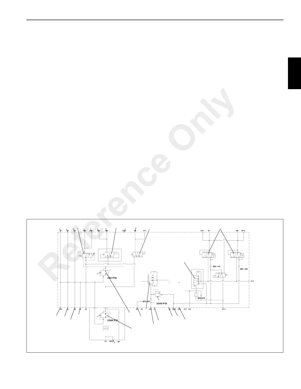
ACCESSORY WITH SWING DIRECTIONAL
CONTROL MANIFOLD
Description
The accessory manifold with swing directional valve
(Figure 2-16) is located on the right side of the turntable. The
manifold contains two adjustable pressure reducing valves,
five 3-way two position solenoid valves, a 3-way four position
swing directional valve, and a check valve.
One pressure reducing valve provides 1.72 MPa (250 psi) for
operation of the swing brake. The other provides 17.2 MPa
(2500 psi) for the pilot circuit.
Each solenoid valve is held in its normally closed position by
a spring. When the solenoid is energized, the plunger
assembly forces the spool to shift, causing the valve to shift.
De-energizing the solenoid causes spring pressure to shift
the spool to its normally closed position.
One two position, three way solenoid valve serves as the
swing brake release valve. This normally closed valve, when
de-energized, prevents hydraulic oil pressure from releasing
the swing brake. When the swing brake switch is off, this
valve opens to allow hydraulic oil pressure to release the
swing brake.
One proportional two position, three way solenoid valve
actuated by the cab swing foot brake proportionally supplies
pressurized oil to the swing drive brake.
The three position four-way swing directional valve is
installed onto the manifold. Both swing working ports have
check valves that are flooded by a.41 MPa (60 psi)
resistance check valve providing make-up oil to the swing
motor for motor over-run when the valve is centered. It
receives oil from pump #1 through swivel port 5. This section
is controlled by two proportional two position, three way
solenoid valves. These valves receive an electrical signal
from the cab armrest controllers.
Maintenance
Removal
1. Tag and disconnect all of the electrical connectors or
manual control levers.
2. Tag and disconnect the hydraulic lines from the valves.
Cap or plug the lines and ports.
NOTE: The swing/steer/brake valve manifold weighs
approximately 10.0 kg (22.0 lb).
3. Remove the capscrews, lockwashers and flatwashers
securing the manifold. Remove the manifold.
Installation
1. Place the manifold on the superstructure side plate and
secure with the capscrews, lockwashers and
flatwashers. Torque the capscrews see Fasteners and
Torque Values, page 1-11.
2. Connect the hydraulic lines to the valves as tagged
during removal.
3. Connect the electrical connectors to the valve as tagged
during removal.
19
4
25
20
3
9
23 2
5
8
6
16
21
10
13
22
14
15
7
1
17
18
12
11
24
26
27
28
8462
FIGURE 2-16
Reference Only

 Loading...


