HYDRAULIC SYSTEM RT540E SERVICE MANUAL
2-34 Published 4-20-2015, Control # 502-01
5
7
23
11
10
8
15
17
13
24
11
21
18
20
12
14
2
22
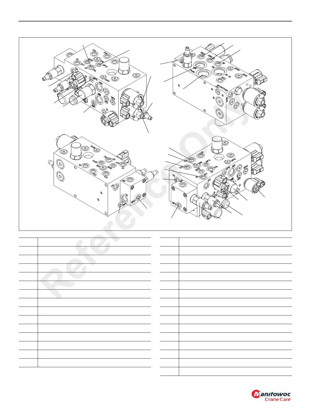
FIGURE 2-16 continued
16
9
6
28
28
29
19
27
3
4
1
8492
17
Item Description
1 Pilot Supply Relief Valve
2 Gauge Port- GP4
3 Swing Brake Relief Valve
4 Solenoid Valve - Swing Brake
5 Solenoid Valve - Swing Brake Release
6 Solenoid Valve - Pilot Supply
7 Gauge Port - GP1
8 Pilot Supply Port - PS
9 Drain - D2
10 Port 2B - Swing Left
11 Port 2A - Swing Right
12 Swing Directional Valve
13 Drain Port - D4 (Swing Motor Pilot Supply)
14 Drain Port - D6 (Hoist/Tele/Lift valve Pilot Supply)
Item Description
15 Drain Port - D7 (Swing Brake/Lift Cylinder Pilot)
16 Drain Port - D3 (Plugged)
17 Gauge Port - GP2
18 Gauge Port - GP5
19 Drain Port - D1
20 Gauge Port - GP3
21 Swing Brake Release Port - SBR
22 Drain Port - D5
23 Swing Brake Supply Port -SBS
24 Tank Port
25 Gauge Port - GP6 (Plugged)
26 Gauge Port - GP8 (Plugged)
27 Proportional Two Position Two Way Solenoid
28 Steering Priority Valve
29 Steer Circuit Load Sense Relief
Reference Only

 Loading...


