UNDERCARRIAGE RT540E SERVICE MANUAL
8-18 Published 4-20-2015, Control # 502-01
brake valve. Bleed every bleeder screw on every caliper/
actuator on every wheel. When you complete a bleeder
screw, go to the next closest bleeder screw on the same
caliper/actuator. When you complete a wheel, go to the
furthest bleeder screw on the next closest wheel.
Pressure Bleeding the Brake System.
NOTE: Before bleeding the brake system, ensure the
hydraulic accumulators are fully charged.
1. Install the bleeding adapter.
2. Using a clean bleeding tank, fill the tank at least half full
with hydraulic oil. Position the tank so it will not have to
be moved again until all bleeding is finished.
3. Connect a 241 kPa (35 psi) air source to the bleeder
tank.
4. Open the bleeder tank valve and bleed all air out of the
hose to be connected to the adapter. Connect the
bleeder hose to the adapter and open the bleeder valve.
5. Connect the end of the bleeder hose to the bleeder
screw on the caliper/actuator. Submerge the other end
in a glass jar partially filled with the proper type of clean
hydraulic oil.
6. Open the bleeder screw and allow fluid to flow into the
jar until it is a solid stream free of air bubbles. Close the
bleeder screw and torque to 11.3 to 13.6 Nm (100 to
120 lb-in).
7. Repeat steps 5 and 6 for the remaining wheel calipers/
actuators.
8. Remove the air supply from the bleeder tank.
NOTE: Close the bleeder tank valve and disconnect the
hose and the bleeder adapter.
9. Remove the bleeder tank and hose.
10. Remove the bleeder adapter.
Manually Bleeding the Brake System
NOTE: Before bleeding the brake system, ensure the
hydraulic accumulators are fully charged.
1. Connect the end of the bleeder hose to the bleed screw
on the caliper. Submerge the other end in a jar partially
filled with clean hydraulic oil.
2. Open the bleed screw on the caliper/actuator and allow
fluid to flow into the jar, while depressing the brake
pedal. Depress the brake pedal and close the bleeder
screw, then release the brake pedal. Torque the bleeder
screw to 11.3 to 13.6 Nm (100 to 120 lb-in).
3. Repeat step 2 until a solid stream free of air bubbles is
obtained.
4. Repeat steps 1 thru 3 for the remaining wheel calipers/
actuators.
SERVICE BRAKES
Description
The brakes utilized on the axles are hydraulic disc-type
brakes. Two brake assemblies are used at each wheel end
on the front axle. One brake assembly is used at the wheel
end on the rear axle. The action of the brake pads riding
against the brake discs acts to slow the rotation of the
wheels.
Maintenance
NOTE: To perform maintenance on the brake caliper,
remove the tire and wheel assembly. Refer to
AXLES in this section.
Removal
Linings
1. Block the wheels.
2. Remove the bolts securing the end plates to one side of
the caliper housing. Remove the end plates.
3. Loosen the bleeder screws to release hydraulic
pressure in the caliper.
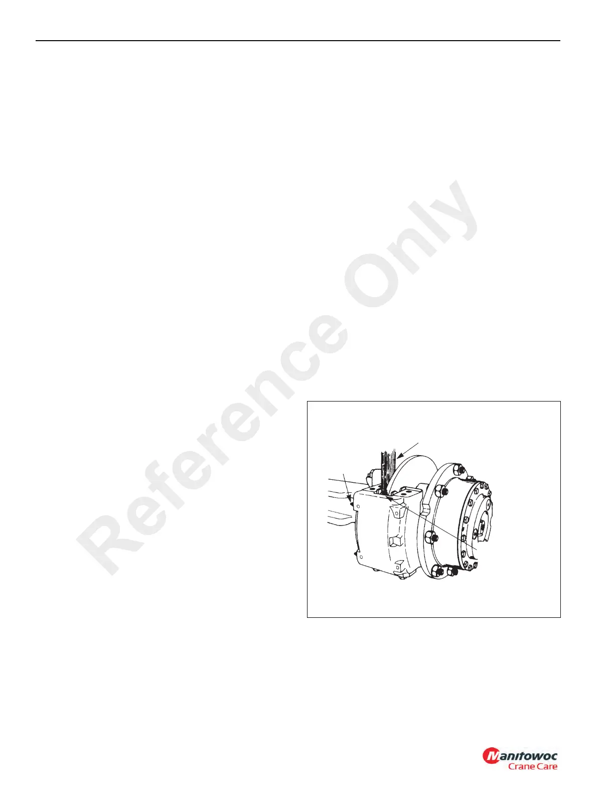
4. Use a piece of wood against the linings as a pry bar to
push the pistons completely into the housing. Tighten
the bleeder screws (Figure 8-13).
5. Remove the linings from the caliper housing. If
necessary, discard the linings.
Loosen
Bleeder
Screws
Wood
Block
Push Wood
Block Against
Linings to Push
Pistons Into
Bores
FIGURE 8-13
Reference Only

 Loading...


