Published 4-20-2015, Control # 502-01 6-13
RT540E SERVICE MANUAL SWING SYSTEM
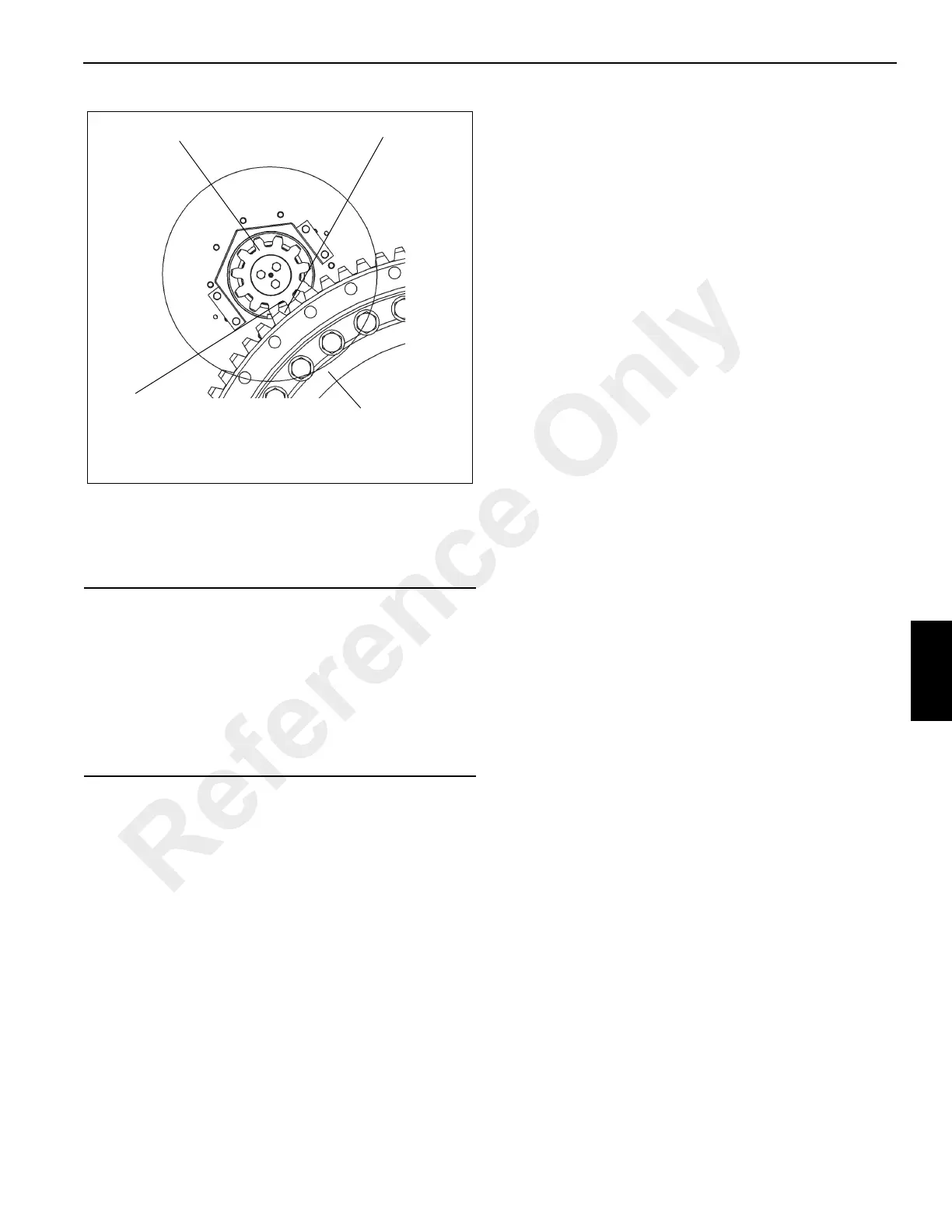
Orient ring gear such that its point of max eccentricity (“high
point”) is located between the swing drives. Position swing
drives so that pinion is centered within cutout in base plate
and motor ports face towards the outboard side as shown.
5. Apply Loctite 271 to the capscrews. Position the two
retainer plates on the bottom of hydraulic swivel spool,
engaging the lugs on the carrier frame, and secure them
to the spool with four capscrew retainers and bolts.
Torque the bolts 298 to 322 Nm (220 to 237 lb-ft). Bend
all the retainer tabs to make contact with the bolt heads.
6. Plug the swivel wiring harness connectors into the
carrier receptacles. Secure the ground wire to the
ground stud using a washer, lockwasher, and nut.
7. Install the clamp securing the swivel wiring harness to
the retainer plate on the bottom of the hydraulic swivel.
8. Connect all water and hydraulic lines to the ports on the
bottom of the swivel as tagged during removal.
9. Install the boom and lift cylinder following the procedures
outlined in Section 4, BOOM.
NOTE: The counterweight structure weighs approximately
3818 kg (8417 lb).
10. Install the counterweight and auxiliary hoist following
procedures outlined in Section 4 of the Operator
Manual.
11. Reconnect the batteries.
12. Check the slew potentiometer in the electrical swivel for
proper orientation. Refer to SWIVELS in this Section
Testing
Activate the crane and check for proper function.
NOTE: If the superstructure does not turn freely after
bearing and pinion replacement, contact your local
distributor.
CAUTION
Do Not Clamp Over Pinion.
• Using shims, set backlash by moving the swing drive
assemblies toward the bearing in order to mesh the
pinion with the ring gear teeth (see Figure 6-5).
• Check tooth engagement squareness and vertical
tooth engagement.
• Remove backlash shims and recheck backlash.
FIGURE 6-4
Maximum Eccentricity Point
.0.20 Thick Shim
By Full Width to Tooth
Engagement (.040) Backlash)
Pinion
6750-3
Bearing
Reference Only

 Loading...


