Published 4-20-2015, Control # 502-01 6-19
RT540E SERVICE MANUAL SWING SYSTEM
7. Plug the connector into the carrier wiring receptacle,
connect the wires as tag during removal. Install the
yellow ground wire to the connector mounting bracket on
the carrier frame using the bolt and star washers taken
of at removal and refer to Grove Engineering
Specification A-829-100386 for proper electrical
termination of grounds.
8. Install the clamp securing the harness to the retainer
plate on the bottom of the hydraulic swivel assembly.
9. Connect the batteries.
10. Activate all systems, cycle all functions, and observe for
proper operation. Adjust the slew potentiometer in
accordance with SLEW POTENTIOMETER
ADJUSTMENT procedures in this Sub-Section.
Preventive Maintenance
It is recommended that a normal inspection of the electrical
swivel collector ring and brush assembly be established. An
example of this could be at approximately 100 to 150 engine
operating hours. When this time limit is reached, perform the
following.
1. Check the collector ring and brush assembly for any
corrosion, pitting, arcing, and wear.
2. Check the collector ring setscrews and ensure they are
tight.
3. Check the brush and arm assembly springs. Ensure
they are holding the brushes firmly against the collector
rings.
Slew Potentiometer Adjustment
1. Rotate the superstructure over the front and engage the
house lock pin.
2. Remove the electrical swivel cover.
3. Disengage the house lock pin and swing the
superstructure approximately 10 degrees to the right
(clockwise). Slowly swing back to the left and engage
the house lock pin.
NOTE: If the superstructure swings past the house lock pin
engaged position, step 3 must be repeated.
4. Loosen the three screws that secure the slew
potentiometer to the mounting plate.
5. Rotate the body of the slew potentiometer until the slew
angle indicates 0.6 ± 0.1 degree.
NOTE: The slew angle indication in step 6 may not be
obtainable due to limited wire length on the
potentiometer, or the electrical terminals
interference with one of the three mounting screws.
If this occurs, reposition the collar set screwed to
the potentiometer shaft and repeat steps 3thru 5.
6. Tighten the three screws that secure the slew
potentiometer to the mounting plate. Install the electrical
swivel cover.
7. Disengage the house lock pin and swing approximately
10 degrees to the left (counterclockwise). Slowly swing
back to the right and engage the house lock pin.
NOTE: If the superstructure swings past the house lock pin
engaged position, step 7must be repeated.
8. If the angle indicated on the console does not exceed ±
1.0 degree, proceed to step 10. If the indicated angle
exceeds ± 1.0 degree, return to step 3.
9. Disengage the house lock pin and swing approximately
10 degrees to the right (clockwise). Slowly swing back to
the left and engage the house lock pin.
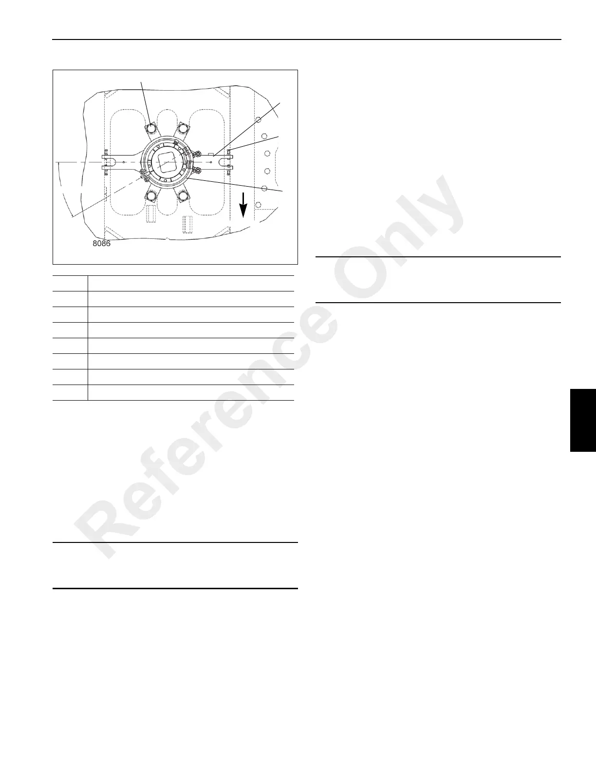
Item Description
1 Swivel
2 Capscrew
3Hex Nut
4 Capscrew
5 Washer
6 Bushing
7 Retaining Plate
CAUTION
It is imperative that the slew potentiometer be adjusted
anytime work is done to the electrical swivel.
TOP OF SWIVEL
FIGURE 6-6
7
2, 3
30° Ref
4, 5, 6
1
Forward
CAUTION
Do not attempt to rotate the slotted shaft in the center of
the slew potentiometer.
Reference Only

 Loading...


