Page 102 OM 780-2
The next-off chiller will be disabled when the next-off active capacity is less than (spare capacity multiplied by spare
capacity factor). Decoupled systems have the additional stage-down requirement that the decoupler line flow rate is
greater than (next-off chiller’s flow multiplied by decoupler stage down flow rate factor). All stage-downs require that
the chiller stage delay time has expired since the last stage-up or stage-down. See Sequencing Logic section on page 78.
System Capacity
System capacity is available in two possible forms. The first indication of system capacity is available for all system
configurations and gives a nominal system capacity. The second indication of system capacity is available for system
configurations with a flow meter in the common supply line and a common return water sensor.
Nominal System Capacity
The nominal system capacity is displayed as Current Row Capacity (Tons) in the stage-up section of the System Status
screen. This is a nominal capacity because it displays the sum total of the capacity of each chiller multiplied by each
chiller’s current percent rated load amps (%RLA). The chiller’s nominal capacity is entered by the operator and represents
the full load capacity of a chiller at one operating condition. The %RLA is a general indication of the percent of full load
that a chiller is currently running. The current row capacity value is displayed to allow you to monitor the stage-up status
of the system, but it also gives you a rough estimate of the cooling load.
Measured System Capacity
The CSM can display a calculated value of the system capacity if the system has the following sensors:
• An optional flow meter located in the common supply line
• An optional common return water temperature sensor
• The required common supply water temperature sensor
The Flow Meter Present Flag and Return Water Sensor Present Flag must be set to true, and the Flow Meter Location
variable must be set to Common Supply Line (all on the I/O Config screen). The Chilled Water Load (Tons) variable will
then be displayed under the Clear CSM Alarm button on the System Status screen. This value is only available on systems
with a flow meter measuring the flow through the common supply line.
Temperatures
The CSM provides both system temperatures (Temperature screen) and, for your convenience, local water temperatures at
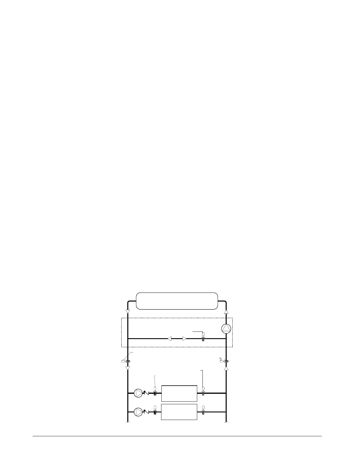
each chiller (Chiller Status screen). Figure 44 and Figure 45 show the locations of these temperature sensors.
Figure 44. Chilled Water Temperature Sensor Locations
Decoupler line temperature
Cooling Loads
Chiller #1
Evaporator
Chilled water return temperature
Chilled water supply temperature
Optional secondary pump/decoupler line
Entering evaporator
water temperature
Leaving evaporator water temperature
Chiller #2
Evaporator
a0139

 Loading...


