Page 60 OM 780-2
4. When constant approach reset is used, the Control Temperature Source variable must be set to “Entering Cond Water”
Note: An OAT sensor and Relative Humidity Sensor must be installed and not in an alarm condition.
Tower Stage Table
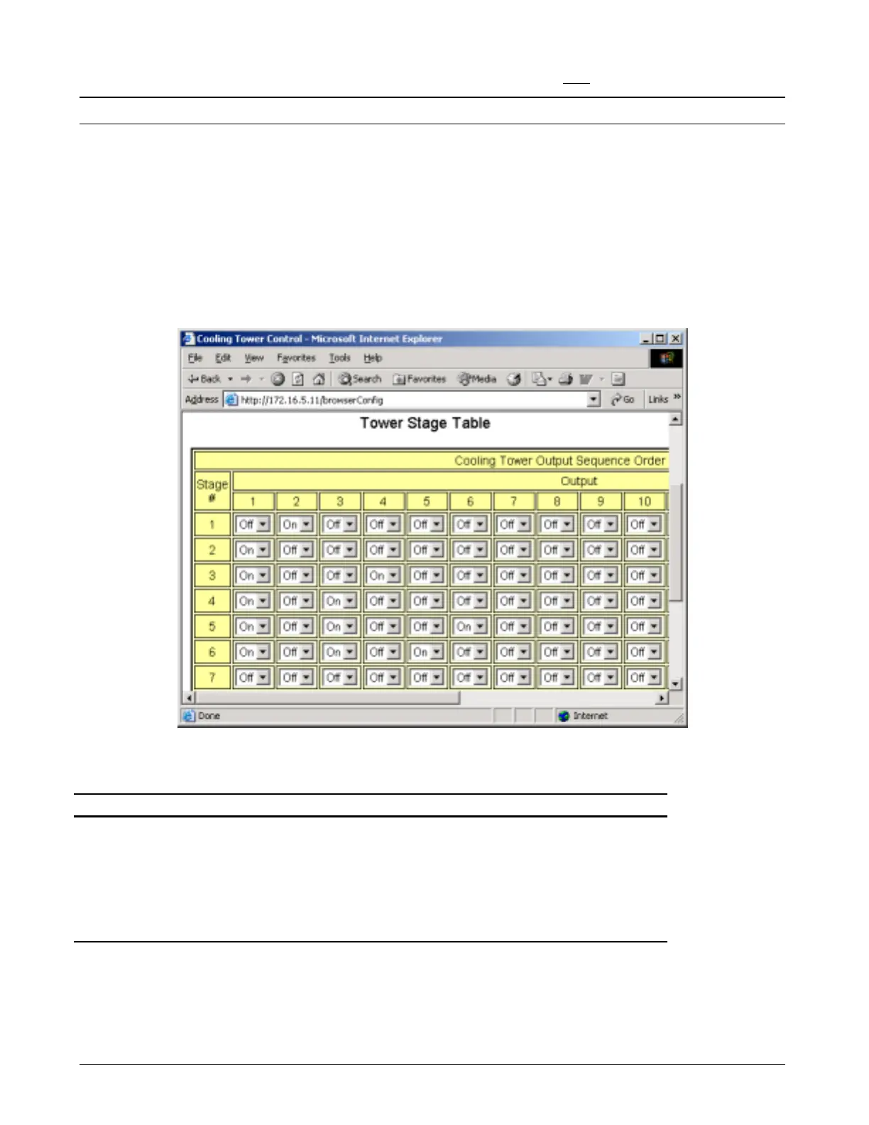
A tower stage is defined as a set of tower outputs. An output might be used to start a fan, set the speed of a two-speed fan
or enable a VFD. In any case, as the stage number increases, the proper outputs should be specified so that the heat
rejection capacity increases. Outputs in the current stage are closed; any other tower outputs are opened.
An example of the tower stage table is shown in Figure 24. Assume that this system has three two-speed fans that are
controlled in six stages. Each fan is assigned two outputs: an odd output for high speed, and an even output for low speed.
Fan #1 has outputs 1 and 2; Fan #2 has outputs 3 and 4; and Fan #3 has outputs 5 and 6. Actual staging operation is shown
in Table 15.
Figure 24. Tower Stage Table (Main>Configuration>Clg Tower Control>Tower Stage Table)
Table 15. Actual Cooling Tower Staging
Tower Stage Result
Stage 1 Fan #1 low speed
Stage 2 Fan #1 high speed
Stage 3 Fan #1 high speed, Fan #2 low speed
Stage 4 Fan #1 high speed, Fan #2 high speed
Stage 5 Fan #1 high speed, Fan #2 high speed, Fan #3 low speed
Stage 6 Fan #1 high speed, Fan #2 high speed, Fan #3 high speed
Tower Staging with VFD’s
VFD’s and the Tower Stage Table
If the CSM will be modulating tower fans with VFD’s, set the Tower VFD Control Flag = Yes and fill in the Tower Stage
Table using the following rules:

 Loading...


