OM 780-2 Page 49
Chiller Controller Setup
Chiller unit controllers are capable of providing soft load control. If soft-loading control is desired from the CSM, the soft
loading features of the chillers must be turned off.
To set up soft loading control
1. Set the soft loading flag to ON.
2. Set the initial soft loading amps as required.
3. Set the soft load ramp time as required.
4. Disable the soft load feature in all of the chiller unit controllers.
Chilled Water Temperature Control
In a system of multiple chillers, each individual chiller should normally maintain its leaving evaporator water temperature
at the same setpoint—even if that setpoint is being reset. The CSM can generate this setpoint (with or without reset) and
send it to every chiller in the system via L
ONWORKS network communications.
Figure 17 shows a flow chart of how leaving evaporator water temperature setpoints are generated and how they flow to the
chiller controllers, which ultimately use them to control capacity and thus water temperature. Notice that the link between
the CSM and the chiller controllers is the Chiller Setpoint.
The CSM provides system water temperatures (Temperature screen) and, for your convenience, local water temperatures at
each chiller (Chiller Status screen). To configure the chilled water temperature control go to the Chilled Water Supply
Temp screen to change the values described in Table 13.
In all cases, each individual chiller controller attempts to maintain its leaving evaporator water temperature at its Active
Setpoint, which is the “working” leaving evaporator water temperature setpoint. Any capacity overrides that are in effect,
such as load balancing or demand limiting, can affect a chiller’s ability to control temperature.
When controlling a chiller using the CSM, the source of the Active Setpoint is the CSM so that the same setpoint is used
throughout the system.
There are many other chiller controller variables that affect leaving evaporator water temperature and load recycle control;
for example, Start-Delta and Max Pull Down rate. For more information, refer to the appropriate MicroTech II chiller unit
controller operation manual (see Reference Documents on page 7).
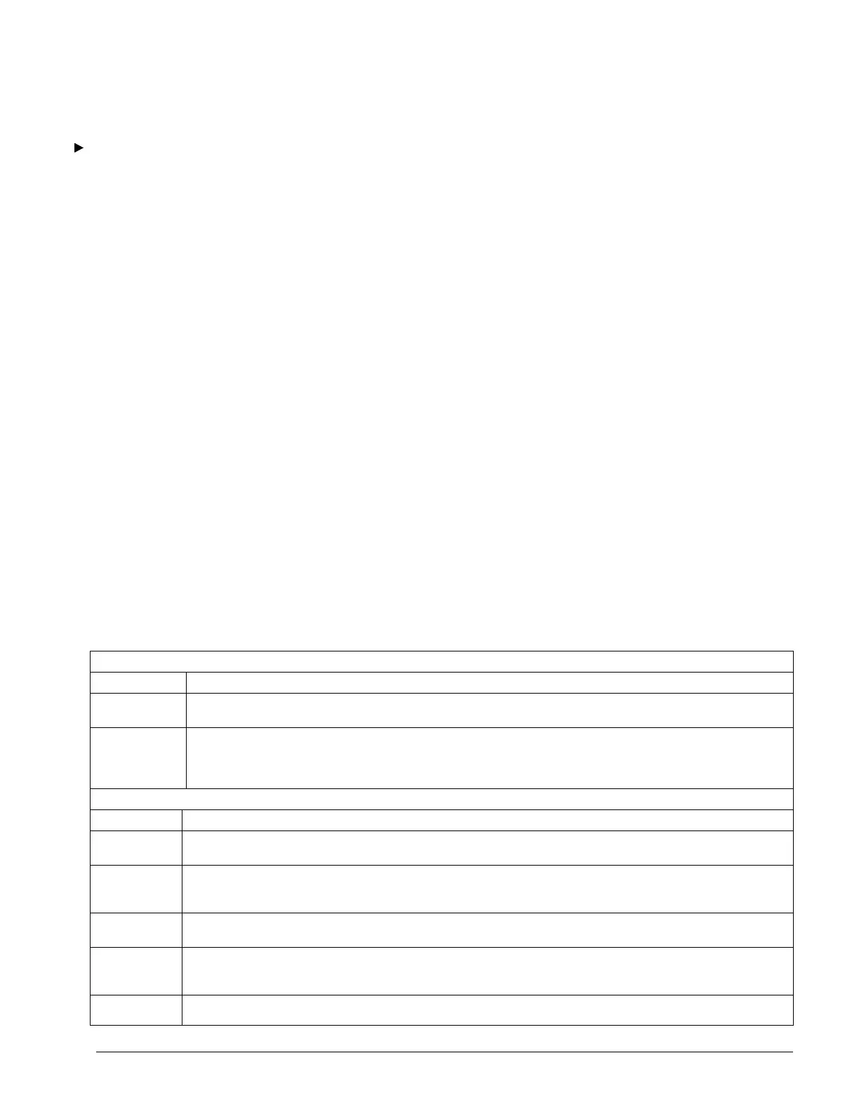
Table 13. Chilled Water Supply Temp (Main > Configuration > Chilled Water Supply Temp)
Chilled Water Supply Temperature Control
Name Description
Operator System
Setpoint
This setpoint becomes the System Setpoint if the Reset Type variable = “None”. Range = Minimum System Setpoint – to -
Maximum System Setpoint. Default = 44.0°F (6.6°C)
Minimum Chiller
Setpoint
This input defines the lowest chilled water temperature setpoint that the
CSM can send to the chillers. You will not be allowed to set the Operator System Setpoint or Minimum System Setpoint property
below this value. Range = 40°F (4.4°C) – to – Minimum System Setpoint (Unless Glycol Flag = yes, then the min = 0°F (-
17.8°C)). Default = 40.0°F (4.4°C)
Chilled Water Supply Temperature Reset
Name Description
Reset Type This input controls what kind of setpoint reset will be applied to determine the System Setpoint. Range = None, External, OAT,
Return Water, Constant Return. Default = None.
Minimum
System Setpoint
This value sets the lowest value that you or a reset function can set the System Setpoint. Also, the System Setpoint will be set to this
value whenever the Reset Override feature is active. Range = 40.0 – 80.0°F (4.4 – 26.6°C) (Unless Glycol Flag = yes, then the min
= 0°F (-17.8°C)). Default = 44.0°F (6.6°C)
Maximum
System Setpoint
This value sets the highest value that you or a reset function can set the System Setpoint. Range = 40.0 – 80.0°F (4.4 – 26.6°C)
(Unless Glycol Flag = yes, then the min = 0°F (-17.8°C)). Default = 54.0°F (12.2°C)
Minimum
System Setpoint
At
This value is used as a limit of the mathematical function used in OAT and Return Water reset types. Range = 0.0 – 99.5°F (–17.8–
37.4°C). Default = 90.0°F (32.2°C)
Maximum
System Setpoint
This value is used as a limit of the mathematical function used in OAT and Return Water reset types. Range = 0.0 – 99.5°F (–17.8–

 Loading...


