Page 92 OM 780-2
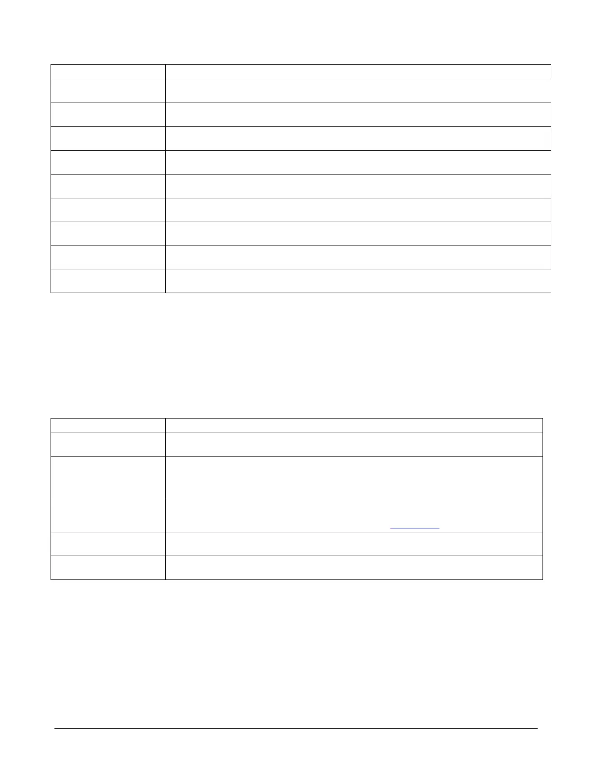
Table 22. Configuring Physical Alarm Outputs (Main > Configuration > Alarms)
Name Description
Horn on Comm Loss Flag If this input = “Horn”, the alarm horn relay (DO-2 on the CSM’s onboard I/O panel) will close whenever a Comm Loss
alarm is present. Range = No Horn, Horn. Default = No Horn
Horn on Fault Alarm Flag If this input = “Horn”, the alarm horn relay (DO-2 on the CSM’s onboard I/O panel) will close whenever a Fault alarm
is present. Range = No Horn, Horn. Default = No Horn
Horn on Problem Alarm Flag If this input = “Horn”, the alarm horn relay (DO-2 on the CSM’s onboard I/O panel) will close whenever a Problem
alarm is present. Range = No Horn, Horn. Default = No Horn
Horn on Warning Alarm Flag If this input = “Horn”, the alarm horn relay (DO-2 on the CSM’s onboard I/O panel) will close whenever a Warning
alarm is present. Range = No Horn, Horn. Default = No Horn
Alarm Output Normal State If this input = “Open”, the alarm output relay (DO-5 on the CSM’s onboard I/O panel) will be open when the CSM
does not have any alarms. Range = Open, Closed. Default = Open
Alarm Output Comm Loss State The alarm output relay (DO-5 on the CSM’s onboard I/O panel) will go to the state defined by this input whenever a
Comm Loss alarm is present. Range = Open, Closed, Slow, Fast. Default = Open
Alarm Output Fault State The alarm output relay (DO-5 on the CSM’s onboard I/O panel) will go to the state defined by this input whenever a
Fault alarm is present. Range = Open, Closed, Slow, Fast. Default = Open
Alarm Output Problem State The alarm output relay (DO-5 on the CSM’s onboard I/O panel) will go to the state defined by this input whenever a
Problem alarm is present. Range = Open, Closed, Slow, Fast. Default = Open
Alarm Output Warning State The alarm output relay (DO-5 on the CSM’s onboard I/O panel) will go to the state defined by this input whenever a
Warning alarm is present. Range = Open, Closed, Slow, Fast. Default = Open
Physical alarm outputs
The CSM has three physical digital outputs on the onboard I/O board that can indicate an alarm by closing a contact
connected to an external device; the Alarm LED Output, the Alarm Horn Output, and the Alarm Output. An LED can be
wired to the Alarm LED output (DO-1 of the CSM’s onboard I/O) which closes when any alarm occurs. A horn can be
wired to the Alarm Horn that can be set to indicate different alarm types in different ways. The Alarm Output can be wired
to a receiving device and also set to indicate different alarm types in different ways.
Table 23. Configuring E-Mail Alarm Notification (Main > Configuration > Alarms)
Name Description
E-mail Alarm Flag When this input is set to Disable, the CSM does not route alarms to the listed E-mail recipients. Range = Disable,
Enable Default = Disable
SMTP Host This input specifies the SMTP host the CSM will use to send E-mail alarms. Contact you IT department for the
proper host name or address. The CSM must be restarted after changing the SMTP host name. Range = any valid
host name or address of SMTP server. Default = 172.16.1.56 (note: this default will need to be changed to the Host
address or name of the SMTP server on your LAN)
From Address This input specifies the “from” address used in sent e-mail alarms. An e-mail account on the SMTP server is
typically required using this same address. Often, an e-mail account named “ChillerSystemManager” is created and
used. Range = valid e-mail address. Default = ChillerSystemManager@nowhere.com
SMTP Server User Name Username associated with the e-mail account used on the SMTP server. May be left blank unless the SMTP server
requires authentication on a send operation.
SMTP Server Password Password for the user named by the SMTP Server User Name property. May be left blank unless the SMTP server
requires authentication on a send operation.

 Loading...


