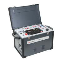
AJ0383DE ZP-AJ01E TRAX
27
5 OPERATING INSTRUCTIONS
3] Press and select e.g. “Inductance”, “Im-
pedance”, “Power factor” or other parame-
ters to get additional information of the test
4] Connect the generator leads to the test
object.
5] Select an appropriate test voltage for the test
object or manually control the voltage (after
pressing ) and observe the excitation
current for e.g. determine saturation/knee-
point.
6] Press to start the generator.
7] Wait for results to stabilize or manually con-
trol the voltage and observe the excitation
current for e.g. determine saturation/knee-
point.
8] Press and read the results.
Note The description above is using an internal cur-
rent measurement channel and measures the
total current generated into the test object.
(GST-GND)
If the test object has two parallel parts e.g. a
winding in a delta configuration, the mea-
sured value is the current going through one
winding in parallel with two series windings.
For measuring excitation current on a single
winding in a delta configuration, an external
current measurement can be used and by
grounding correctly a UST measurement can
be performed.
Warning
When using 2.2 kV output and external
ammeter, its is ABSOLUTELY MANDATORY
to ground black terminal and connect the
external current measurement channel
to the grounded side of the generator/
winding.
Short-circuit/leakage reactance
measurements
1] Select 0-10 A AC generator.
2] Select Gen I measurement channel, set to
freq, to measure the excitation current and
use the data for calculations.
3] Select Ch 1, set to freq, for voltage meas-
urement. (Gen U can be used for the meas-
urement but for higher accuracy a separate
voltage measurement using Ch 1 is recom-
mended).
4] Press and select e.g. Inductance, Imped-
ance, Reactance or other parameters to get
appropriate data for the test.
5] Connect current leads and voltage sense
leads to 0-10 A output and channel 1 voltage
input respectively. At sample, place voltage
sense leads “inside” current connectors.
6] Short appropriate low voltage winding (e.g.
first measurement of a YNyn0, measure 1U-
1N, short 2U-2N).
7] Select an appropriate test current for the test
object. For power transformer windings, typ-
ical test current are 1 to 5 A for short-circuit
impedance/leakage reactance measurements.
Note Max compliance voltage is 250 V. When mea-
suring small transformers with high winding
resistance you need to select a lower current,
(typically 100 mA or lower) to not trip the
generator.
8] Press
9] Wait for results to stabilize.
10] Press and read results.
11] Move to next phase and continue the test.
Note This measurement can also be performed
by using the 250V generator and adjust the
voltage until the preferred test current is
achieved.
Zero-sequence impedance
measurements
1] Select 0-250V AC generator and 55 Hz.
2] Select Gen I measurement channel, set to
freq, to capture an hold the excitation cur-
rent and use the data for calculations.
3] Select Ch 1, set to freq, for voltage measure-
ment.
(Gen U can be also used for the measurement

 Loading...