42 TRAX ZP-AJ01E AJ0383DE
5 OPERATING INSTRUCTIONS
tap-changers, define type, location, num-
ber of taps, tap voltages and which taps
that should be measured in the actual
test.
C] If the configuration is not supported at all
for leakage reactance tests it is still possi-
ble to run manual and connect and short
based on previous experiences with the
actual transformer and/or configuration.
Example:
3-w transformer with DETC (5 taps) on HV, OLTC (19
taps) on LV, no taps on tertiary
HV-LV Impedance
Per-phase measurements
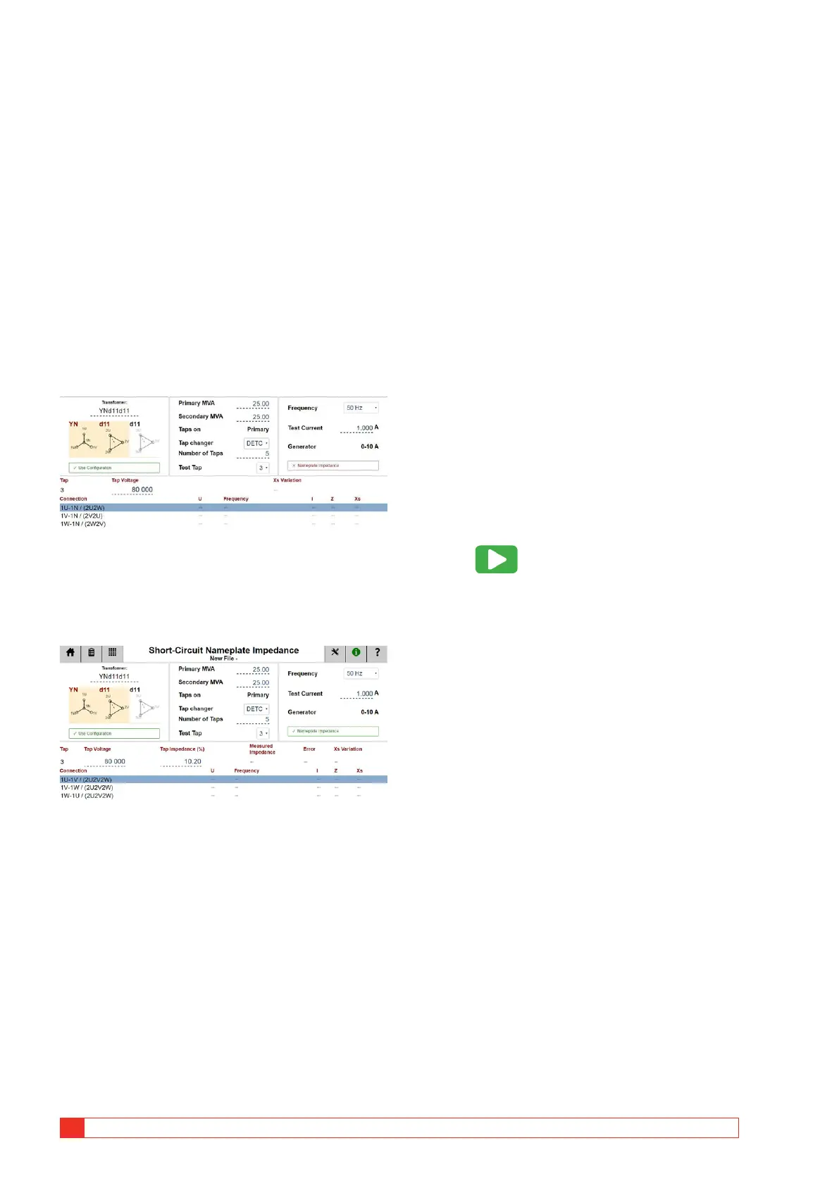
When configuration is selected, TRAX suggest
measurements per-phase and the variation in leakage
reactance, Xs, is calculated and displayed.
Three-phase equivalent
By providing a value for as per nameplate
“Impedance” the app automatically selects three-
phase equivalent model and the results can be
compared with the transformer nameplate.
Three-phase equivalent works for Y and delta con-
figurations with the three LV terminals (but NOT the
neutral) shorted. Make sure the shorts are good with
low resistance since LV current will be test current
multiplied with transformer ratio.
Three-phase equivalent model does not work for
Zigzag configurations and the resulting impedance
cannot be compared with nameplate.
Step-by-step instructions
1] Select transformer configuration (and num-
ber of taps, however this test is normally
done on nominal tap only).
2] Enter transformer nameplate information
including: “Impedance”, Nominal HV voltage
(kV), Power (MVA) and Impedance (%).
3] Confirm cable connections/hook-up.
4] Select test frequency:
Default and recommended frequency for
short-circuit measurements is line frequency
and winding variation is calculated for Xs
(leakage reactance). For higher frequency
comparisons of Rs and Ls, select 500 Hz.
Please note that winding variation is still
calculated for Xs.
5] Select test current (default 1 A). Short-circuit
impedance is not pending test current. Typ-
ical test current are 1-5 A. Note that maxi-
mum output voltage is 250 V which may be
limiting the maximum test current for small
transformers with high HV winding resist-
ance.
6] Press to start the generator and meas-
ure.
7] Reconnect cables to next phase.
8] Save results.
9] After all three phase have been tested, compare
calculated impedance value with nameplate.
Deviation should typically be < 3%. Also compare
Xs values for the three phases, winding variation
should typically be < 3%.

 Loading...